Open Flux now, switch Copilot to “Next-gen” and see how it handles your next design challenge. The sooner you try it, the more your feedback can shape the next leap in AI-powered hardware design.
In 2019, we scratched our heads at the current state of hardware tools. Why did they look like they were designed in the 1980s? Ohhhh they were. We asked ourselves... what if we started from scratch? What if designing hardware was seamless, intuitive, even delightful? What if we could automate all the mundane work? That was our dream.
In 2019, we scratched our heads at the current state of hardware tools. Why did they look like they were designed in the 1980s? Ohhhh they were. 😬
We asked ourselves... what if we started from scratch? What if designing hardware was seamless, intuitive, even delightful? What if we could automate all the mundane work? That was our dream.
Fast forward three years, and boom! We opened up to everyone. Since then, the numbers have been wild. Over 100,000 of you have joined, creating a whopping 177,000 projects! And shout out to the 3,200 businesses riding this wave with us. We've even got PCBs designed in Flux going to space soon! 🚀
Let’s take a look back at some of the company’s major highlights that you helped us fulfill!
From the very beginning, we always knew that Flux was only going to be as successful as the community that we built around it. That’s why we started with a private beta: so that we could build a tight-knit community of people who shared the same vision as us as we grew the product. If it weren’t for that group of beta users in the very beginning, we would not be here with you today.
In February 2023, we took our next big step when we emerged from private beta. For the first time ever, anyone in the world was able to test out Flux, and the response was overwhelming. This was our first major step towards our ultimate goal of truly democratizing hardware design for everyone.
We’ve always sought to take the “hard” out of hardware, and it was obvious that existing tools came up short of that vision. We knew we had to think bigger, which is why we came up with Flux Copilot: the industry’s first and only AI PCB design assistant.
When we introduced Copilot, its capabilities were unprecedented, and the response from YOU was fantastic. Over 15,000 users have now worked with Copilot, and it’s tackled a whopping 130,000 questions.
But we didn't stop there. Copilot evolved to not just provide feedback but to take action for you. With Copilot’s ability to wire up schematics for you, users were finally able to avoid the tedium of wiring schematics and spend more time on what really matters. We want to put the magic back in hardware design, and generative AI with Copilot has been one huge step toward that goal.
Meet Gerald, a software engineer behind Vendo King Manila, a vending machine business in the Philippines. Before Flux, he struggled with jumbled boards and too many jumper wires. With no prior PCB design experience, Gerald dived into Flux and crafted his own board. He says, “With Flux, I made our PCB easily. No more wire mess or production problems!” That's a big win! 🚀

Then there's Robert, a software engineer who loves computers, old-school games, web development, and 3D printing. He's the guy behind ControllerAdapter.com, making cool stuff for game controller fans. Thanks to Flux, Robert easily designs and shares his creations.

Looking back at the last four years, it’s amazing to see how far this community has come together.
While what we’ve done has been transformative, what’s really exciting are the infinite possibilities that lie ahead of us. We’re currently exploring the very edge of AI's capabilities in hardware design, and who better to do it with than our incredible community?
We have some exciting things planned for the future, and one thing is for sure: the best has yet to come.
If you want to help Flux continue to grow and change hardware design, tell your friends about us! Let them know about Flux and encourage them to sign up and get involved.
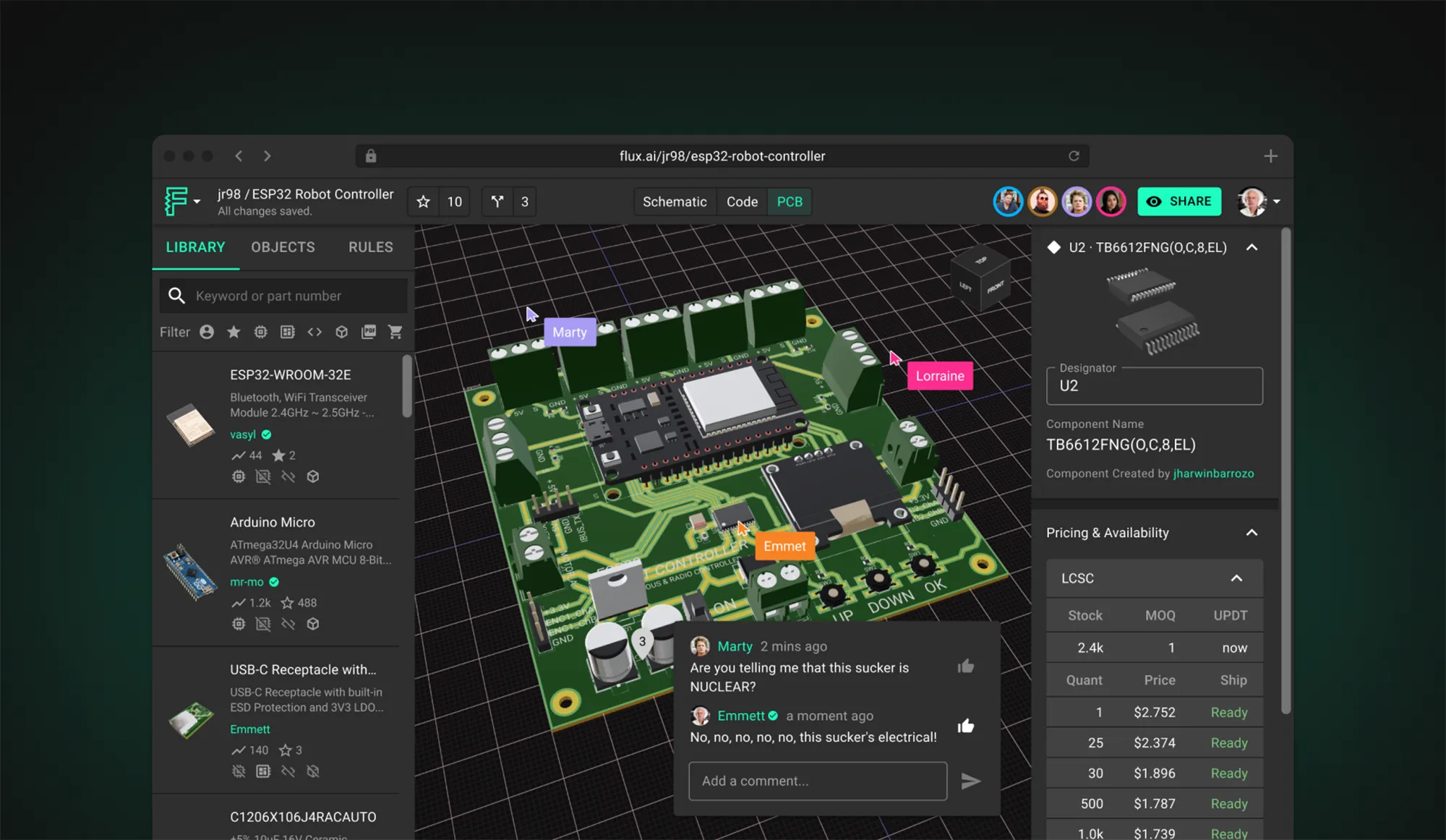
Today, we're proud to announce a significant upgrade to Flux Copilot: Copilot can now understand datasheets and reference them in its responses. This means you get more accurate responses when asking Copilot questions about specific parts. This enables you to directly utilize the wealth of data often hidden in the layers of these dense technical documents.
Copilot now offers unprecedented precision by incorporating information from datasheets. This enables you to directly utilize the wealth of data often hidden in the layers of these dense technical documents. Here’s some of our favorite use cases:
@copilot What is the power consumption of the ESP32 in sleep mode?
@copilot What's the power-up sequence for the PMIC in U1?
@copilot How do I configure an interrupt on a pin for U4?
@copilot What is the maximum frequency I can reach without an external crystal on U6?
@copilot What are some layout recommendations I need to follow for IC3?
@copilot What’s the voltage range for vddio on U4?
@copilot Can U2 withstand intense operating temperature even without heatsink?
Check out our full list of our favorite Copilot Prompts to get more ideas!
Copilot now gives you more transparency about where it gets its information from. Instead of just giving you an answer, Copilot now cites its sources.
We believe transparency is key to enhancing trust and confidence in AI technologies. Now, when Copilot pulls information from a datasheet it directly cites that source in the response. This feature allows you to verify the accuracy of the information provided, tracing it back to the original context in just a click.
By including the source of information directly in Copilot's response, we provide a clear, traceable path back to the original document. This heightened transparency gives you the confidence to trust Copilot's responses and the ability to dive deeper into the source material whenever you choose.
With this update also comes the ability for Copilot answer questions about how to use Flux by referencing our documentation. So, instead of getting stuck and searching documentation, you can stay in the flow and get the help you need without leaving your project! Now you can ask questions like:
@copilot I want to put custom silkscreen on my PCB. How would I do that?
@copilot I can't find part on the library what do I do?
@copilot How do I start a simulation?
At Flux, our goal has always been to empower the masses by making hardware design more accessible to all. With this newest update to Copilot, you now have greater accuracy, transparency, and control over your AI design assistant, and the sky is the limit!
If you want to learn more about Copilot and how to use it, reach out to us on Slack, or check out any of these resources:

Effortlessly calculate parallel and series resistor values with our accurate, user-friendly tool designed to optimize circuit performance and streamline electrical design processes.
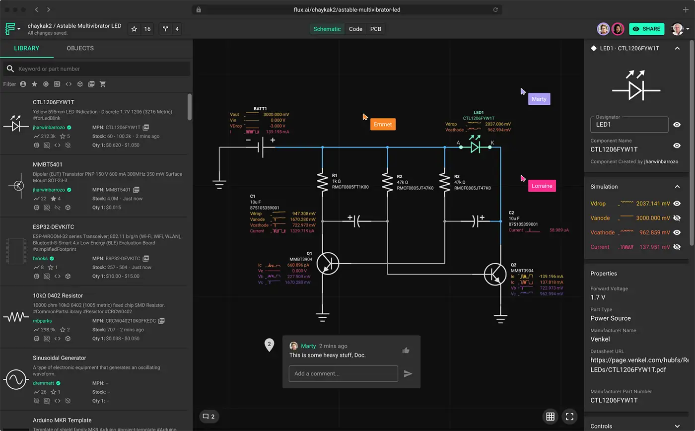
💡 Did you know that one of the capabilities of Flux Copilot, an AI powered hardware design assistant is its ability to calculate the total resistance between any two points in your schematic diagram? You can effortlessly determine the overall resistance, making complex calculations a breeze. Try Flux now, and best of all, it's completely free!
This means you don't need to do any calculations or formula anymore. Through a simple chat interface, just simply ask Copilot,
"@copilot what is the total resistance across terminal 1 and terminal 2?"
and wait a moment for Flux Copilot to response with the calculated total resistance value. It can even determine series or/and parallel resistor configuration automatically. It's like your holding a physical ohm meter and reading the actual resistance of a circuit. See it for yourself!
As electronics enthusiasts and professionals, we are always on the lookout for tools that can streamline our design process and improve our understanding of circuit behavior. The parallel and series resistor calculator is one such indispensable tool that enables efficient and accurate analysis of resistor networks. In this comprehensive guide, we will explore the concept of parallel and series resistors, the importance of resistor calculators, and the benefits they provide.
Parallel resistors refer to resistors connected end-to-end, sharing the same voltage across their terminals. When resistors are connected in parallel, their combined resistance is less than the smallest individual resistor's value.
The total resistance in a parallel configuration is given by the formula:
Series resistors are connected in a way that the end terminal of one resistor is connected to the starting terminal of the next resistor. In series configuration, the current flows sequentially through each resistor, and there is only one current path through the entire resistor network. The resistors should beconnected end-to-end, with no junction points or branches between them. Worth noting that same current flows through each resistor in this configuration, and the voltage drop across each resistor is proportional to its resistance.
The total resistance in a series configuration is simply the sum of the individual resistances:
Manual calculations can be tedious, time-consuming, and error-prone, particularly when dealing with multiple resistors or complex circuits. This is where parallel and series resistor calculators come into play, offering valuable benefits such as:
Parallel and series resistor calculators are designed to provide quick and accurate results for resistor networks. These calculators generally include the following features:
These resistor calculators are valuable tools for professionals and hobbyists alike. Some common applications include:
Parallel and series resistor calculators are essential tools for anyone working with electronic circuits. They simplify calculations, save time and effort, and reduce the risk of design errors. By understanding their significance and choosing the right calculator, you can ensure that your projects run smoothly and efficiently. So, go ahead and harness the power of these indispensable tools to elevate your circuit design skills to new heights.

Easily calculate resistor values with Flux online Resistor Color Code Calculator. This powerful tool saves time and eliminates errors for electronics enthusiasts and professionals.
Resistors are ubiquitous components in the world of electronics, playing a crucial role in regulating current flow, setting voltage levels, and protecting other components in circuits. As you dive into projects or repairs, it's important to understand how to identify the value of a resistor to ensure proper functionality and avoid potential issues. One of the most common methods to determine a resistor's value is by interpreting its color code. In this article, we will guide you through the process of identifying the value of a resistor using its color code, helping you become proficient at reading these codes and ensuring the success of your electronic endeavors.
Resistors are measured in ohms (Ω), the unit of electrical resistance. The ohm represents how much a resistor opposes or resists the flow of electric current in a circuit. Resistance values can range from a fraction of an ohm (e.g., milliohms or mΩ) to many millions of ohms (e.g., megaohms or MΩ). When selecting a resistor for a particular application, it's important to choose one with the appropriate resistance value to achieve the desired effect in the circuit.
The color code for resistors is a universal method employed to signify a resistor's resistance value, tolerance, and its temperature coefficient for 6-band resistor. This system features a sequence of color bands printed on the resistor's surface, simplifying the identification of the resistance value without requiring extra markings or tags.
The color code system employs 10 colors, each assigned a numerical value:
Resistors typically have 4, 5, or 6 colored bands:
You can determine the resistor's resistance value, tolerance, and temperature coefficient by reading the colored bands and referring to the color code chart. This system makes it simple and efficient to identify and select resistors for various electronic applications.
To read the resistor color code effectively, it's essential to understand how the bands represent different attributes of a resistor. Let's dive deeper into the significance of each band and how to interpret them:
Becoming proficient at reading resistor color codes requires practice. Here are some tips to help you along the way:
By familiarizing yourself with the resistor color code system and practicing reading the bands, you'll be well-equipped to identify resistor values and select the appropriate components for your electronic projects.
We’re incredibly excited to announce that we have decided to open up Flux and move out of private beta! What does this mean? If you’re a current user of Flux - nothing will change for you. For new users, this means that we’re now allowing anyone and their team to signup!
Hey everyone! We’re incredibly excited to announce that we have decided to open up Flux and move out of private beta! What does this mean? If you’re a current user of Flux - nothing will change for you. For new users, this means that we’re now allowing anyone and their team to signup! Exiting the private beta is a huge milestone for all of us and we have a lot to thank you and the community for. Over the course of the 2-year private beta, we’ve had 25,000 engineers join and over 240,000 projects created in Flux! We can’t thank you enough for taking a chance and joining a generational effort of reimagining how PCBs get made. It’s your candid feedback, ideas, and encouragement that enabled us to dare to change this and build Flux. And we are just getting started, so consider this our warm up lap 🚀!
In terms of pricing, nothing will change. Our mission is to take the hard out of hardware and enable anyone to design PCB boards and make electronics hardware. As such we are fully committed to always have a no nonsense free tier that allows you to host up to 10 private projects and unlimited public projects. If those 10 private projects are not enough, we offer a Pro tier at $12/mon per editor that features unlimited private projects. Now what about team tiers and features you ask…bring the upvotes!
When we started out 3 years ago, we knew that we were embarking on a monumental effort that would require early and ongoing input from hardware engineers. That’s why we decided to launch Flux embarrassingly early and build in public, learn in real time, and build a community that pushes back against the forces of stagnation in EDA/CAD tooling and is ready for change.
Wow! Did you deliver. ❤️ Everything we’ve built was inspired by insights we gained during the series of events we hosted, video calls, heated slack debates, and passionate email exchanges. And frankly the naysayers who told us that change is impossible; that it should be resisted; that it goes against human nature - change isn’t optional. It happens all the time. And we live to prove the naysayers wrong!
We knew that to make the big leaps in PCB design we wanted, we would need to build it from the ground up with re-usability, speed, and collaboration at the forefront. This took time, but we think it is worth it. Some of the major features that make Flux’s PCB editor different from others include:
In terms of performance improvements, we were able to make huge gains to enable projects of increasing complexity with less lag. Our goal is for Flux to provide better performance than native applications and be available on any device type, from high end CAD workstations to your phone or tablet.
It’s been incredibly inspiring to see what people have been building in Flux, and how fast they’ve been able to design projects. Kerry Chayka, who worked on the iPhone motherboard for 7 years, puts it well “As a one man hardware startup, Flux gives me the super powers I need to work as fast as an entire team. Customers come to me with rough ideas of what they want and I’m able to build a product mockup before our first meeting even happens. I can do something that usually takes 2 months in half a day”.
At Flux, we’re inspired by a no nonsense and plug-and-play philosophy that makes it 10x faster and easier for anyone to create, share, and remix projects with others. If you think about how easy it is today for a 12 year old to build an iPhone app, our dream is to make it as easy for them to build their own iPhone. That’s what drives us to host competitions such as the recent Custom Arduino Shield Competition to create awesome shields, HATs, and wings...to have more of the building blocks for your projects available. Here are some of our favorite submissions:
Our current competition is focused on Energy Harvesting if you’re interested in getting involved. We’re looking for projects that can capture any type of energy, such as solar, kinetic, thermal, or RF; and no, wall chargers don’t count.

Over the last 2 years, we’ve been incredibly fortunate to grow our team from 10 to 22 with former engineers from Apple, NASA, and Facebook from all over the world. I think what makes our team unique from other software companies is that we love and build hardware! From high intensity strobe lights to drum machines, we’re always using Flux to build our own projects, which makes it easier to figure out what needs to be improved.
Want to get involved? You can check out open full-time positions here. There’s also plenty of part-time opportunities and sponsorships available to those who are interested. Feel free to reach out to Nico on Slack if you want to figure out how to plug in.
This milestone is really just one step forward towards our mission to take the hard out of hardware. We still have a long way to go, and I hope that the collaboration with the community will only continue to grow.
Just because we’re exiting private beta doesn’t mean we have everything figured out! We’re constantly looking for ways to improve and your feedback is absolutely critical to making an EDA tool that everyone loves. You can always submit feature requests or report bugs and we’ll do our best to address them quickly. Here’s a handful of the improvements we’re focused on.
Interested in helping us take the hard out of hardware? Tell your friends! Let them know that we’re opening up public availability and encourage them to signup and get involved. Talk about us on your favorite forums and other online communities, or post about us on social media. Every little bit helps!
Thanks again for all the support during the private beta. We really appreciate all the candid feedback, your patience, and your encouragement as we push forward.
Onward 🚀
Matthias & Lance
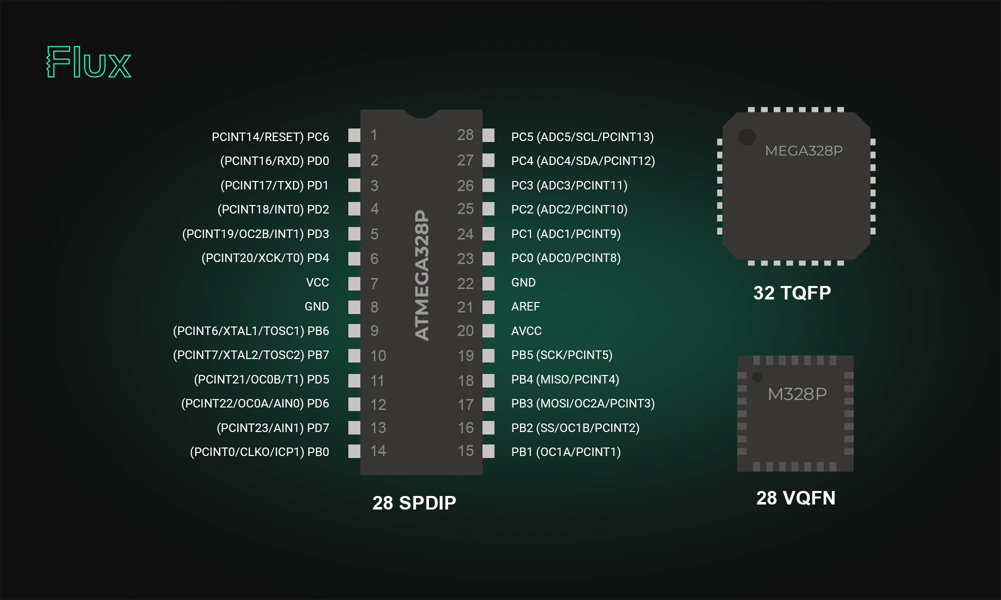
The ATmega328p stands out in the microcontroller world; our post breaks down its datasheet and pinout, offering valuable insights into its functionality and versatility. Learn how this powerful microcontroller can enhance your projects.
At the core of many electronic projects lies the ATmega328p, an 8-bit microcontroller belonging to Atmel's AVR series running off of a Reduced Instruction Set Computer (RISC) architecture. RISC architecture is advantageous due to its simplicity, which results in faster execution, improved compiler optimization, and better support for parallelism.
The ATmega328p is equipped with 32KB of ISP (In-System Programmable) flash memory, 1KB of EEPROM (Electrically Erasable Programmable Read-Only Memory), and 2KB of SRAM (Static Random-Access Memory).
Embedded systems often require the ability to store data persistently. The ATmega328p addresses this need with its onboard EEPROM. This non-volatile storage space is crucial for storing data that needs to persist across power cycles.
Developers can utilize the EEPROM for storing configuration parameters, calibration data, or any other critical information that requires retention.
With 32 pins, the large number of digital and analog I/O pins is a key strength of the Atemga328p. The device boasts 23 general-purpose I/O (GPIO) lines, including analog inputs for sensor integrations. With a total of 6 analog input pins, developers can seamlessly interface with various sensors, converting real-world analog signals into digital data for processing.
There are two VCC pins (pin 4 and pin 6) and one AVCC pin (pin 18) for voltage supply, three GND pins (pin 3, pin 5, and pin 21) for grounding, and additional pins for 22pF capacitors, vital for stabilizing the 16MHz crystal oscillator.
The ATmega328p excels in managing inputs and outputs with three bi-directional GPIO ports, two 8-bit ports—PortB and PortD–and one 7-bit port–PortC. These ports serve as I/O interfaces, allowing users to control or read from external devices. Each I/O port pin may be configured as an output with symmetrical drive characteristics, or an input with or without pull-up resistors of 20 - 40 K ohms. Each bit in a Port corresponds to a specific pin, granting granular control over the connected peripherals. Understanding the DDR (Data Direction Register) is crucial for manipulating the ports. It determines whether each pin in a port operates as an input or output. For instance, setting a specific bit in DDRB to 1 configures the corresponding pin in PortB as an output.
Ensuring a stable 5V supply is vital for consistent performance, and the ATmega328p comes equipped with robust voltage regulation capabilities. The microcontroller operating voltage range is 1.8V to 5.5V, making it adaptable to various power supply configurations.
The ATmega328p offers several power-saving modes, allowing developers to tailor power consumption based on project requirements. These modes are particularly beneficial for energy-sensitive applications, extending battery life, or enabling solar-powered solutions.
Notable features of the ATmega328p include a plethora of options for serial communication (SPI, I2C, USART), two 8-bit Timer/Counters, one 16-bit Timer/Counter, and a 6-channel 10-bit A/D converter (ADC) enabling analog signal acquisition.
The atmega328p supports SPI, I2C, and USART, essential for communicating with other microcontrollers or modules.
A dedicated SPI interface enables high-speed, full-duplex communication. The following table outlines the key pins associated with SPI:
Integrating SPI-enabled devices, such as external flash memory or display modules, becomes seamless with the ATmega328p.
I2C support further extends the microcontroller's communication capabilities. The ATmega328p's I2C pins are:
This protocol is invaluable in projects requiring communication with multiple devices on the same bus.
USART enables serial communication and is crucial for interfacing with devices like GPS modules or Bluetooth modules. The USART pins on the ATmega328p are:
The ATmega328p provides flexibility in choosing between internal and external clock sources. This choice, such as opting for an external 16MHz crystal, significantly influences precision and power consumption.
Built-in timer counters enable the ATmega328p's time-sensitive capabilities. These timers provide accurate timing intervals and pulse-width modulation (PWM) functionality.
The ATmega328p’s 6-channel 10-bit Analog-to-Digital Converter (ADC) significantly enhances its capability to acquire and process analog signals. This ADC functionality is instrumental in translating real-world analog data, such as sensor inputs, into digital values that can be processed by the microcontroller.
This module is capable of translating analog voltages into a 10-bit number ranging from 0 to 1023, based on the inputted range of expected voltages (from 0 V to the voltage of the VCC). The microcontroller provides flexibility in choosing from six input sources, but only one channel can be converted at a time. The ADC module operates with a conversion speed of approximately 15,000 samples per second (15 ksps), ensuring swift and efficient signal processing.
The ATmega328 and ATmega328P are microcontrollers from the same family but have some differences:
The ATmega328P is not discontinued. While there was an indication on a distributor's website (Mouser) suggesting that the ATmega328P-MU variant is scheduled for obsolescence and will be discontinued by the manufacturer, this information should be interpreted with caution.
The Arduino Uno board, one of the most popular Arduino boards, uses the ATmega328p as its central processing unit. This integration has played a significant role in popularizing the ATmega328p, making it synonymous with user-friendly yet powerful microcontroller projects.
While Arduino offers easy access to the ATmega328’s capabilities, there are some applications that require utilizing the ATmega328p standalone, without the Arduino framework. Programming the ATmega328p standalone has a steeper learning curve, but provides a more granular and customized approach.