Flux Blog

News, resources, and company updates

Flux + GPT-5 (Beta)

Open Flux now, switch Copilot to “Next-gen” and see how it handles your next design challenge. The sooner you try it, the more your feedback can shape the next leap in AI-powered hardware design.

|
August 11, 2025
Thank you! Your submission has been received!
Oops! Something went wrong while submitting the form.
Essential Tips for Utilizing SMD in PCB Manufacturing

Essential Tips for Utilizing SMD in PCB Manufacturing

Let’s start by exploring the benefits of SMDs, as opposed to traditional through-holes:

| Benefit | Description | | :=== | :=== | | Miniaturization | SMDs enable electronic miniaturization, crucial for space-constrained applications. | | High-Density Assembly | SMDs allow for high-density PCB assembly, optimizing component placement for increased overall density. | | Improved Electrical Performance | Shorter lead lengths in SMDs reduce parasitic elements, enhancing high-frequency performance and signal integrity. | | Reduced Signal Interference | Compact size and direct PCB placement minimize loop areas, reducing electromagnetic interference EMI. | | Automated Manufacturing | SMDs are compatible with automated pick-and-place, ensuring efficient and precise mass production with cost savings. | | Lower Weight and Cost | SMDs contribute to lighter devices, and automated assembly reduces manufacturing costs.| | Enhanced Thermal Performance | SMDs with exposed metal pads improve thermal dissipation, enhancing overall thermal performance. | | Better Mechanical Stability | SMDs, soldered directly to PCBs, provide superior mechanical stability, making them more resistant to shocks, vibrations, and mechanical stresses. |

SMD Packaging for Passive Components

Surface Mount Device (SMD) packaging for passive components, such as resistors, capacitors, and inductors, involves a variety of package types:

Chip Resistors and Capacitors (Standard Ceramic Packages)

  • Packages: The most common SMD package for chip resistors and capacitors is the ceramic chip package. It comes in various standardized sizes, such as 0402, 0603, 0805, and 1206.
  • Materials: Typically made of ceramic materials with conductive layers for electrodes and dielectric layers for capacitors.
  • Advantages: Compact size, suitable for high-density applications.

Tantalum Capacitors

  • Packages: Tantalum capacitors come in SMD packages like the molded tantalum chip (MTC) and molded tantalum leadframe (MTL) packages.
  • Materials: Tantalum-based dielectric material with a metal case for encapsulation.
  • Advantages: Higher capacitance values in a compact size, suitable for applications requiring stable capacitance over a wide temperature range.

Aluminum Electrolytic Capacitors

  • Packages: SMD aluminum electrolytic capacitors are available in various configurations, including cylindrical and chip-type packages.
  • Materials: Aluminum-based electrolyte with a metallic case.
  • Advantages: Larger capacitance values compared to ceramic capacitors, suitable for applications requiring higher energy storage.

Multilayer Ceramic Capacitors (MLCC)

  • Packages: MLCCs are available in various standard sizes, including 0402, 0603, 0805, 1206, and larger.
  • Materials: Multilayered ceramic structure with alternating layers of ceramic and conductive material.
  • Advantages: High capacitance density, suitable for high-frequency applications and decoupling.

SMD Packaging for Active Components

| Category | Package | Types | Materials | Advantages | | :=== | :=== | :=== | :=== | :=== | | Transistors | SOT (Small Outline Transistor) | SOT-23, SOT-89, SOT-223 | Plastic or epoxy resin with metal leads | Compact size, suitable for low to medium-power discrete transistors | | Integrated Circuits (ICs) | QFN (Quad Flat No-Lead) | Compact, leadless with exposed thermal pad on the bottom | Plastic or ceramic with metal leads/pads | Compact, suitable for high-density integration, various pin counts, and configurations | | | TQFP (Thin Quad Flat Package) | Flat, square-shaped with gull-wing leads | | | | | SOIC (Small Outline Integrated Circuit) | Small, rectangular with gull-wing leads | | | | | SSOP (Shrink Small Outline Package) | Similar to SOIC but with a smaller body size | | | | Microcontrollers | LQFP (Low-profile Quad Flat Package) | Common sizes: 32, 48, 64, 100 pins | Plastic or ceramic with gull-wing leads | Good balance between size and ease of soldering, suitable for microcontroller applications | | Ball Grid Array (BGA) | BGA (Ball Grid Array) | PBGA (Plastic BGA), CBGA (Ceramic BGA) | Plastic or ceramic with solder balls | High pin count, compact design, excellent thermal performance, suitable for high-performance applications | | Chip-on-Board (COB) | COB (Chip-on-Board) | Bare semiconductor chips mounted on PCB, wire bonding | Semiconductor chips and wire bonds | Compact, cost-effective for high-volume applications, flexibility in design |
Close-up of an electronic motherboard with various components such as capacitors, diodes, and chips, including a central processing unit under a copper heat sink.
Motherboard utilizing surface mount technology

Challenges with Surface Mount Devices

SMDs come with their own set of challenges during assembly and use:

  • Tombstoning: Tombstoning occurs when one end of a passive SMD component is vertically displaced during reflow soldering, resembling a tombstone. This anomaly may arise from uneven heating profiles, inadequacies in solder paste deposition, or irregularities in component placement precision.
  • Solder Bridging: Solder bridging involves unintended connections between adjacent pads, leading to short circuits. Root causes include excessive solder paste application, suboptimal stencil design, or inadequate implementation of solder mask features.
  • Skew and Misalignment: Skew and misalignment issues materialize when SMD components deviate from precise placement on PCB pads during the pick-and-place process. These discrepancies can result in compromised solder joints and consequential performance degradation.
  • Insufficient Solder Joints: Incomplete or inadequate solder joints may occur due to factors such as insufficient solder paste deposition, suboptimal reflow soldering conditions, or inaccuracies in component placement. These deficient joints can yield intermittent electrical connections or outright failures.
|
February 15, 2024
RS485: A Technical Overview

RS485: A Technical Overview

This blog post explores the RS485 communication standard, renowned for its ability to facilitate long-distance, multidrop networking with enhanced noise immunity, making it a preferred choice for industrial settings. Dive into the post to understand RS485's key features and advantages over older protocols.

RS485 is engineered to overcome the limitations inherent in older serial communication standards, such as RS232 and RS422. RS485's facilitates communication between more than two devices, a feature central to the concept of multidrop networking.

actual rs485 connector, its physical appearance.

RS485 Electrical Characteristics

| Category | Number | :=== | :=== | | Differential Voltage Levels | Minimum 200 mV | | Common Mode Voltage Range | -7V to +12V | | Maximum Data Rates | Up to 10 Mbps (short distances) | | | Up to 100 kbps (1200 meters) | | Termination Resistor Value | 120 ohms (at each end) | | Maximum Cable Length | Up to 1200 meters (data rate-dependent) | | Maximum Number of Nodes | Up to 32 (without repeaters) | | Driver Output Current | ±1.5 mA to ±250 mA | | Receiver Input Sensitivity | ±200 mV | | Driver Output Voltage Swing | 1.5V to 5V | | Receiver Input Resistance | 12 kΩ |

Key Characteristics

  • Differential Signaling. One of the most noteworthy features of RS485 is its use of differential signaling. This method involves transmitting each bit of data as a difference in voltage across the two wires of atwisted pair. Unlike single-ended signaling, where the signal is measured against a common ground, differential signaling measures the voltage difference between the two wires,significantly mitigating the impact of external noise.

    The principle behind differential signaling is relatively straightforward. Any external electrical noise typically induces similar electrical disturbances on both wires of the twisted pair. Since RS485 receivers interpret signals based on the voltage difference between these wires, common-mode noise is effectively canceled out. This characteristic makes RS485 particularly suited for environments with high electromagnetic interference, ensuring reliable data transmission even under challenging conditions.
  • Half-Duplex Communication. RS485 operates under a half-duplex communication mode. While the network can handle two-way communication, it cannot transmit and receive data simultaneously. In a half-duplex RS485 system, each device on the network takes turns in sending or receiving data. This mode of operation is a deliberate design choice that caters to the multidrop nature of RS485 networks.

    The half-duplex configuration allows for a simpler and more cost-effective network design, especially crucial in industrial applications where long cable runs and multiple devices are common. Although this means that data cannot flow in both directions simultaneously, the high-speed capabilities of RS485 ensure that the time lag in switching between sending and receiving modes is negligible for most practical applications.

Technical Specifications

Physical Layer

  1. Twist Pair Wiring - The physical infrastructure of RS485 relies on twisted pair wiring. In a twisted pair cable, two conductors are intertwined in a helical form, which significantly diminishes the effect of electromagnetic radiation and noise. The twist rate, or the number of twists per unit length, plays a role in determining the effectiveness of this noise cancellation.

    Twisted pair wiring in RS485 can be shielded or unshielded. Shielded twisted pair (STP) cables come with an additional layer of conducting material that acts as a shield against external noise. Unshielded twisted pair (UTP) cables, while more vulnerable to noise, are often preferred in less demanding environments due to their lower cost and ease of handling.

    The cable impedance, typically around 120 Ohms for RS485, requires matching of  the impedance of the cable with the terminating resistors at each end of the network to prevent signal reflections, which can degrade communication quality.
  2. Voltage Levels and Signal Encoding - RS485 defines specific voltage levels for logical high (1) and logical low (0) states in digital communication as at least 200 millivolts required for a valid signal, with a range typically extending up to ±6 volts. This range allows RS485 to achieve a balance between sufficient signal strength for reliable data detection and low enough voltages to minimize power consumption and reduce the risk of circuitry damage.

    Signal encoding in RS485 converts digital data into electrical signals for transmission. The most common encoding techniques include Non-Return-to-Zero (NRZ) and Bi-phase encoding. NRZ is straightforward, representing a logical 1 or 0 by a high or low voltage, respectively. Bi-phase encoding, on the other hand, incorporates transitions within each bit period, thereby aiding in clock recovery and synchronization in the absence of a separate clock line.

Data Link Layer

  1. Master-Slave Communication - At the data link layer, RS485 commonly employs a master-slave communication protocol. In this architecture, one device (the master) initiates and controls the communication with one or more slave devices. The master device sends commands or queries to the slaves, and the slaves respond accordingly. This hierarchical structure ensures organized and collision-free communication, especially in systems with multiple devices.
  2. Multi-Drop Configuration - RS485's ability to support multi-drop: allowing for multiple devices (up to 32, or more with repeaters) to be connected to a single communication bus without requiring additional select lines. Each device on the network has a unique address, and the master device can direct communication to a specific slave or broadcast to all devices. This topology is highly efficient for systems where centralized control and data collection from various points are necessary–i.e. systems with decentralized data sources and/or a variety of sensors and devices.
    1. Full-Duplex Capability - While RS485 is inherently a half-duplex standard, it can be extended to support full-duplex communication by using four-wire cabling (as opposed to the standard two-wire configuration). In a full-duplex RS485 system, two twisted pairs are used: one pair for transmitting data and the other for receiving. This allows simultaneous bi-directional communication, effectively doubling the data throughput. Full-duplex RS485 is advantageous in applications where rapid and continuous two-way data exchange is critical.

Comparison with RS232 and RS422

Pinout differences of RS485, RS232 and RS422. These standard protocols in serial communication devices and applications.

RS232 and RS422 are two other major serial communication protocols. While RS232 is limited in distance and device connectivity, offering point-to-point communication typically within 50 feet, RS485 extends this capability to 4000 feet and allows up to 32 devices on a single bus. RS422, similar to RS485 in terms of distance and voltage levels, differs primarily in its support for multi-drop configurations. RS422 is more suited for point-to-point or multipoint unidirectional communication, lacking the bidirectional, multi-drop capability inherent to RS485. 

Practical Applications: Industrial Use Cases

Profibus and Other Industrial Protocols

RS485 is the physical layer for several industrial protocols. 

  • Profibus (Process Field Bus) is a leading standard in industrial automation and capitalizes on RS485's robustness and reliability for field bus communication, facilitating data exchange among automation systems and field devices like sensors and actuators. RS485's ability to support long cable lengths and multiple devices makes it an ideal foundation for Profibus.
  • Modbus RTU and DNP3 leverage RS485's physical layer characteristics to ensure secure and efficient communication in automation systems, SCADA (Supervisory Control and Data Acquisition) systems, and other industrial control systems. 

Integration with Analog Devices

While RS485 inherently supports digital communication, it is often used in conjunction with analog-to-digital converters (ADCs) and digital-to-analog converters (DACs) to interface with analog sensors and control devices. This is useful when analog signals from sensors (like temperature, pressure, or flow sensors) need to be digitized for processing and monitoring in digital control systems. 

Considerations for Installation and Maintenance

Proper termination of the RS485 network is essential to prevent signal reflections, which can degrade communication quality. This involves matching the characteristic impedance of the cable with terminating resistors at each end of the network.

Cable selection and layout are also critical. Factors such as the type of twisted pair cable (shielded or unshielded), the environment where the cable is installed (including potential exposure to EMI), and adherence to proper grounding practices are critical for optimal network performance.

Maintenance of RS485 networks involves regular checks for any deterioration in cable integrity, connectors, and terminations. Additionally, Ensuring network reliability involves managing device limits and adhering to cable length specifications.

|
February 16, 2024
What is RS232?

What is RS232?

Despite newer technologies like USB and Ethernet, RS232 remains widely used due to its simplicity and broad compatibility. It's crucial in industries, scientific instruments, networking gear, and legacy computers. This protocol's reliability makes it the go-to for many applications. In this blog, we'll explore why RS232 continues to be relevant in our tech-savvy world.

RS232 Architecture and Components

Devices in RS232 Communication

  • Data Terminal Equipment (DTE) - DTE devices, such as computers, terminals, or network equipment, serve as the starting or ending point in RS232 communication. They are configured to transmit and receive data in accordance with the RS232 standard.
  • Data Circuit-Terminating Equipment (DCE)
    • Modems and Their Role - In RS232 communication, modems are typical DCE devices. They modulate digital data from a DTE into analog signals for transmission over telephone lines and demodulate incoming analog signals back into digital data.
    • Handshaking Protocols (RTS/CTS, DSR/DTR) - Handshaking protocols like RTS/CTS and DSR/DTR are essential for synchronized communication between DTE and DCE. These protocols help in managing the readiness of devices for communication and the flow of data, thus preventing data loss or overflow.

Serial Ports

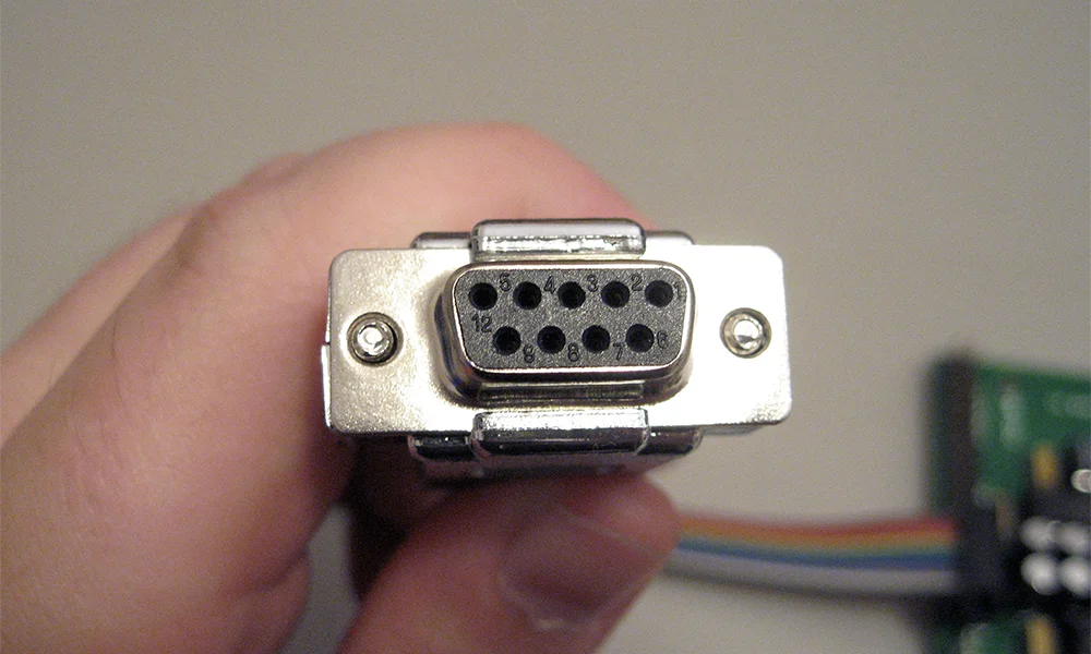
Physical Characteristics of Connector Types (DB9, DB25)

The RS232 standard utilizes two primary types of connectors: DB9 and DB25. 

  • The DB9 connector, a smaller 9-pin version, is prevalent in current applications. 
  • Conversely, the DB25 connector, featuring 25 pins, was more commonly used in earlier RS232 implementations. 

Each connector type serves a specific application–modern, smaller applications or complex setups that need more control, respectively–with different pin configurations for transmitting data, receiving data, and various control signals.

pinout of RS232 db9 connector

Pinouts

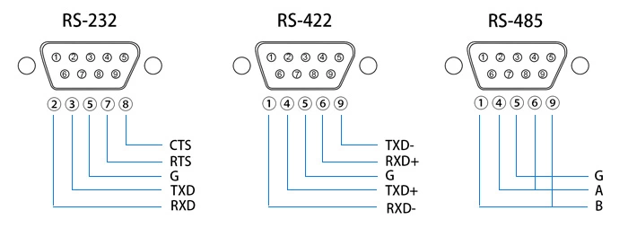
Pinouts in RS232 connectors define the functionality of each pin. These configurations vary between DB9 and DB25 connectors. The standard pinouts include pins designated for Transmit Data (TXD), Receive Data (RXD), and several control signals like Request to Send (RTS) and Data Terminal Ready (DTR).

DB9 Pinout for RS232 Communication:

| DB9 Pin Number | Signal Name | Description | | :=== | :=== | :=== | | 1 | Protective Ground | Connects to the chassis ground | | 2 | Transmit Data (TXD) | Data sent from DTE to DCE| | 3 | Receive Data (RXD) | Data received by DTE from DCE | | 4 | Data Terminal Ready (DTR) | DTE ready for data transmission | | 5 | Signal Ground | Common ground for signals | | 6 | Data Set Ready (DSR) | Indicates DCE is ready | | 7 | Request to Send (RTS) | DTE requests permission to send | | 8 | Clear to Send (CTS) | DCE grants permission to send |

Data Transmission

  1. Transmit Data (TXD) - The TXD pin is responsible for sending data from the DTE to the DCE. This data transmission occurs in a serial format, meaning data bits are sent sequentially over a single channel.
  2. Receive Data (RXD) - Conversely, the RXD pin facilitates the reception of data by the DTE from the DCE. Notably, as a bidirectional, half-duplex system, RS232 allows you to send and receive data on the respective lines, but not simultaneously.
  3. Control Signals (RTS, DTR) - RS232 also incorporates several control signals to manage the flow of data. The Request to Send (RTS) and Data Terminal Ready (DTR) signals are instrumental in initiating and maintaining the data communication process.

RS232 Communication Protocol

Serial Communication Basics

  • Start and Stop Bits. A start bit indicates the beginning of a data packet, followed by the actual data bits. Optionally, a parity bit is included for error checking, and the packet ends with one or more stop bits. This ensures that both the sender and receiver are synchronized in data transmission.
  • Parity Bits. Parity bits are used in RS232 to detect errors in data transmission. Depending on the configuration, the system can use no parity (no additional bit is added for error-checking), even parity (an extra bit is added to ensure the total number of bits (including the parity bit) is even), or odd parity (an extra bit is added to ensure the total number of bits (including the parity bit) is odd). This bit checks the number of 1's in the data bits and adjusts accordingly to match the selected parity mode, providing a basic form of error checking.
  • Flow Control
    • Hardware Flow Control:
      • RTS/CTS Handshaking - In RTS/CTS (Request to Send/Clear to Send) handshaking, the RTS signal from the transmitting device alerts the receiver of impending data transmission. Upon readiness, the receiving device responds with the CTS signal, clearing the sender to proceed. This method effectively prevents data overflow by managing the pace of data transmission.
      • DTR/DSR Handshaking - Similarly, DTR/DSR (Data Terminal Ready/Data Set Ready) handshaking works on the same principle. DTR is sent by the DTE to indicate its readiness, and DSR is the DCE's response, signifying its preparedness to communicate.
    • Software Flow Control
      • XON/XOFF Protocol - The XON/XOFF protocol is a software-based alternative to hardware flow control. It utilizes specific control characters (XON for start and XOFF for stop) to manage data transmission. This method is particularly useful in scenarios where the hardware lacks dedicated pins for flow control, the communication setup is straightforward, or compatibility with legacy systems is essential. 

Applications and Relevance of RS232 Today

Despite the advent of more advanced communication protocols like USB and Ethernet, RS232 remains used due to its simplicity and wide compatibility. It's commonly used in industrial and scientific instruments, networking equipment, and legacy computer systems.

Troubleshooting Common RS232 Issues

Common issues in RS232 communication include misconfigured baud rates, incorrect parity settings, and improper cable connections. Troubleshooting these problems requires a systematic approach, often involving checking cable connections, verifying device configurations, and using diagnostic tools like serial port monitors.

|
February 15, 2024
Importance of Voltage Drop Calculations

Importance of Voltage Drop Calculations

A voltage drop calculator is an essential tool for assessing the decrease in voltage across a conductor, ensuring electrical devices receive adequate power for optimal operation. Read our blog to learn more.

Voltage drop in electrical circuits can lead to various issues, affecting the performance and lifespan of electrical equipment:

  • Inductive loads like motors and ballasts may overheat if they operate below their voltage rating, leading to shorter equipment life and increased costs. 
  • Sensitive electronic devices, such as computers and printers, can experience data loss or even failure if subjected to under-voltage conditions.
  • Resistive loads, such as heaters and incandescent lighting, will not provide their expected power output when operating under voltages.

Factors Affecting Voltage Drop

  1. Conductor Material: Different materials have different resistivities, which affects the voltage drop. Copper and aluminum are common materials used in electrical conductors, with copper having a lower resistivity than aluminum.
  2. Wire Size: The diameter of the wire (or wire gauge) affects its resistance. Larger wire sizes have less resistance and, therefore, less voltage drop.
  3. Length of the Wire: Longer wires have more resistance, leading to a greater voltage drop.
  4. Current: The amount of current flowing through the wire also affects the voltage drop. Higher current leads to a greater voltage drop.

National Electrical Code (NEC) Guidelines on Voltage Drop

Here's a table summarizing the NEC guidelines on voltage drop:

| Area | NEC Guiddeline | | :=== | :=== | | Branch Circuits | Conductors should be sized to limit voltage drop to a maximum of 3%, with the total voltage drop for branch circuits and feeders not exceeding 5% (NEC 210-19(a) FPN No. 4).| | Feeders | Conductors should be sized to limit voltage drop to a maximum of 3%, with the total voltage drop for feeders and branch circuits not exceeding 5% (NEC 215-2(d) FPN No. 2). | | Phase Converters | Voltage drop from the power supply to the phase converter should not exceed 3% (NEC 455-6(a) FPN). | | Grounding Conductors | If circuit conductors are increased in size to compensate for voltage drop, the equipment grounding conductors must also be increased in size (NEC 250-122(b)). | | Motion Picture/TV Studios | For 60/120 volt systems, branch circuit conductor voltage drop must not exceed 1.5%, and the combined voltage drop of feeder and branch circuit conductors must not exceed 2.5% (NEC 530-71(d)). | | Fire Pumps | Operating voltage at the terminals of a fire pump controller must not be less than 15% from the voltage rating of the controller during motor starting, and operating voltage at the terminals of the motor must not be less than 5% from the voltage rating of the motor when operating at 115% of its full-load current rating (NEC 695-7). |

Using a Voltage Drop Calculator

Voltage drop calculators typically require you to input the following parameters:

  • Type of circuit (single-phase, three-phase, or DC). Single-phase AC is used in homes, three-phase AC is used in industries for efficiency, and DC is typically used in electronics and batteries.
  • Conductor material (e.g., copper, aluminum)
  • Size of the conductor (e.g., AWG, kcmil)
  • Length of the conductor
  • Current or load in amperes

The calculator then computes the voltage drop based on the inputs and provides the result in volts or as a percentage of the initial voltage. Some calculators also provide the minimum conductor size required to limit the voltage drop to a specified level.

Calculating Voltage Drop

Ohm’s Law Method – Single-Phase Only

Voltage drop of the circuit conductors can be determined by multiplying the current of the circuit by the total resistance of the circuit conductors: The Ohm’s law (V = I*R) method only applies for DC current and cannot be used for three-phase circuits.

Transforming the formula, we have:

V = 2*R*I*L

Where: 

  • V ​is the voltage drop in volts (V)
  • L is one way length of circuit (source to load) in thousands of feet (Kft.)
  • I is the current in amperes
  • R is conductive resistance in ohms/ 1000 ft.

Three-phased system

Generally, with the cable information (length, size, material, operating temperature, and cover type), we can find its resistance and inductance from the reference tables. Three-phase AC power, with three sine waves offset by 120 degrees, is used in industrial and commercial settings for more efficient power distribution and to run heavy machinery.

V=3*I*L*(R*cosθ+X*sinθ)

For balanced three-phase circuits, a simplified calculation  is:

V =3*I*Z*L/1000

Where:

  • V is the voltage drop in volts 
  • I is the current in amperes
  • R is conductive resistance in ohms/ 1000 ft. obtained from tables.
  • X is conductor inductive reactance in ohms/1000 ft. obtained from tables.
  • L is one way length of circuit (source to load) in thousands of feet (Kft.)
  • Z is  complex impedance in ohms/ 1000 ft. obtain from Tables.
  • Cosθ = Power Factor. Power factor measures the efficiency of power usage, defined as the cosine of the phase angle between voltage and current in an AC circuit.

Conclusion

The significance of calculating voltage drop extends beyond basic electrical design; it's a key factor in the overall performance and safety of electrical systems. Excessive voltage drop is a common culprit behind inefficient system performance, equipment malfunctions, and even safety hazards, which can lead to costly repairs and downtime. Furthermore, meeting the stipulations of electrical codes and standards, which dictate maximum allowable voltage drop levels, is non-negotiable for electrical professionals. Ensuring devices operate within these guidelines means that voltage drop calculations are not just a matter of efficiency but of compliance and safety as well.

|
February 28, 2024
What Is a Functional Block Diagram and Why Is It Critical in System Design

What Is a Functional Block Diagram and Why Is It Critical in System Design

This blog will explore functional block diagrams, their pivotal role in system design, the symbiotic relationship with ladder logic, structured text, and the broader realm of PLC programming. Why FBDs are so important within complex systems.

What is Meant by Functional Diagram?

A functional block diagram is a schematic representation that delineates the principal functions of a system and the flow of data between them. It serves as a cornerstone in system engineering, simplifying the visualization of complex interactions within systems. FBDs are characterized by their use of labeled blocks connected by lines indicating dataflow, making them an intuitive means for depicting system operations.

The advantages of function block diagrams are that they’re very easy to follow and understand. They are generally laid out to mimic a specific process thus making it easy to understand for those who don’t have a background in plc programming.

In essence, an FBD breaks down large systems into manageable, functionally discrete blocks, facilitating a modular approach to system design. This modularity is crucial, allowing designers to focus on individual functions without being overwhelmed by the system's overall complexity.

What Are the Three Main Components of a Functional Diagram?

The potency of a functional block diagram lies in its simplicity and clarity, achieved through three fundamental components:

  1. Function Blocks: These are the primary elements representing specific functions within the system, such as calculations, logical operations, or data processing tasks. Each block encapsulates a distinct functionality, abstracting the underlying complexity.
  2. Input and Output Connections: Function blocks are interconnected through input and output lines, symbolizing the flow of data and control signals between blocks. These connections illustrate how the output from one block serves as input to another, revealing the system's dataflow dynamics.
  3. Labels and Annotations: Descriptive labels and annotations accompany function blocks and connections, providing essential details about the functions performed and the nature of the data being transferred. This textual information enriches the diagram, making it a more informative and effective communication tool.

The Symbiosis with Ladder Logic and Structured Text

FBDs do not exist in isolation; they are part of a larger ecosystem of programming languages and representation techniques used in the programming of programmable logic controllers (PLCs). Ladder logic, with its origins in electrical wiring diagrams, offers a graphical method that is intuitive for those with a background in electrical engineering. It depicts control logic in a format resembling a ladder, with rungs representing logical operations.

Structured text, another facet of PLC programming, is a high-level textual programming language that resembles traditional computer programming languages. It allows for complex instructions and algorithms to be implemented in a more familiar syntactic form.

FBDs complement these programming paradigms by providing a visual overview of system logic and dataflow, serving as a bridge between the conceptual design and the detailed implementation in ladder logic or structured text. This synergy enhances the understandability, development efficiency, and maintainability of PLC-based systems.

FBDs in the Context of Programmable Logic Controllers

PLCs stand at the forefront of industrial automation, controlling machinery and processes with precision and reliability. In the domain of PLC programming, FBDs play a pivotal role, offering a graphical method for designing and implementing control logic.

An example of programmable logic controller PLC functional block diagram FBDs

FBDs align perfectly with the operational paradigm of PLCs, which are inherently designed to execute logic operations based on real-time data inputs. The visual nature of FBDs facilitates the rapid development and troubleshooting of PLC programs, enabling engineers to map out complex control strategies in a more intuitive and less error-prone manner.

Moreover, the adoption of FBDs in PLC programming underscores the importance of a clear and structured approach to system design. By visualizing the functional architecture of a system, engineers can ensure that all components interact harmoniously, leading to more robust and reliable PLC-based control systems.

The Evolution of FBDs and Future Directions

As system complexity continues to escalate, the role of functional block diagrams in system design is not only preserved but also expanding. The integration of FBDs with advanced simulation tools and software development environments is enhancing their utility, allowing for more dynamic and interactive system modeling.

The future of FBDs is likely to witness further integration with artificial intelligence and machine learning technologies, enabling smarter and more adaptive systems. As these advanced systems become more prevalent, the clarity and efficiency offered by FBDs will become even more critical in navigating the complexity of modern system design.

Conclusion

Functional block diagrams are a testament to the power of visual representation in the realm of system design. By distilling complex system functionalities into comprehensible blocks and illustrating the dataflow dynamics, FBDs provide a foundation for designing, implementing, and maintaining sophisticated systems. Their symbiotic relationship with ladder logic, structured text, and PLC programming languages enhances their utility, making them an indispensable tool in the engineer's toolkit.

|
February 21, 2024
Revolutionizing IoT Design: Flux Brings Arduino-Based Matter Projects to Life

Revolutionizing IoT Design: Flux Brings Arduino-Based Matter Projects to Life

If you're a lover of smart home devices, you're likely buzzing with excitement over Arduino's recent collaboration with Silicon Labs. We are too, and we’re even more excited to bring the power of this collaboration to life on Flux. As of today, we’re excited to announce that engineers can fully design Arduino-based Matter boards with Flux.

What is Matter and Its Significance in IoT?

The Matter protocol is growing to become a cornerstone of the Internet of Things (IoT) and smart home industries, offering a unified, secure, and reliable framework for connected devices. Developed by the Connectivity Standards Alliance (CSA), Matter was developed to simplify the complexity of IoT by ensuring that devices from various manufacturers can seamlessly communicate with each other.

At its core, Matter is an IP-based connectivity protocol that leverages common networking technologies such as Ethernet, Wi-Fi, and Thread to facilitate communication among smart devices. By adopting a universal approach, Matter enables devices to interact over existing networks, removing the need for proprietary bridges or gateways. This interoperability is achieved through a standardized application layer that operates on top of these networks, ensuring devices can understand each other regardless of the manufacturer. Even Zigbee devices can connect with Matter using a gateway device.

Prior to the introduction of Matter, the smartthings market was extremely fragmented, with myriad communication protocols leading to compatibility issues and a challenging user experience. Consumers would find themselves locked into a single ecosystem or struggle to integrate new devices into their existing setups. For example, a connected home might have to choose between Apple's ecosystem, with Siri, the Apple Homekit and the Homepod Mini, or Google's ecosystem, with Google Assistant, Google Home, and Google Nest. A smart plug that might support Amazon Alexa-enabled smart speakers might not support smart lighting from Nanoleaf.

Matter addresses these pain points by providing a common language for smart home devices, fostering an environment where products from different ecosystems can coexist and operate in harmony.

Silicon Labs and Arduino Democratize IoT and Matter

The news that has us so excited is Silicon Labs and Arduino’s recent partnership aimed at democratizing the IoT through the Matter protocol.

The partnership focuses on integrating Silicon Labs' advanced hardware with Arduino's extensive libraries and development environment to support Matter. On Arduino’s side, their team created a custom library and Arduino core for Matter-supported Silicon Labs microcontrollers. The major hardware involved in this partnership are Silicon Labs’ MG24 Series Wireless SoCs and the MGM240 Wireless Modules, as well as supported development boards including the xG24 Explorer Kit and the SparkFun Thing Plus Matter MGM240P.

Even more exciting is that, in the near future, the two companies will be releasing a brand new Arduino Nano board based around the MGM240 module.

Ultimately, the partnership is so important because it underscores the growing importance of Matter in the IoT and smartthings ecosystems. By combining Silicon Labs' cutting-edge wireless solutions with Arduino's accessible development tools, this alliance aims to empower developers, from hobbyists to professionals, to create innovative, Matter-compliant smart home products with ease.

Unleashing IoT and Matter with Flux

Like the CSA, Flux is fully invested in democratizing technology. So now it’s Flux’s turn to contribute to the IoT community.

We’re excited to be supporting Arduino and Silicon Labs’ partnership by introducing a new Matter-compatible hardware lineup to the Flux community.

With available devices including the MG24 SoC, the MGM240 module, and development boards such as the xG24-EK2703A Developer Kit and the SparkFun Thing Plus Matter, Flux is your home for all things IoT. Not to mention our already-existing support for dozens of other components and modules from Arduino, Raspberry Pi, Seeed Studio, and more.

But sometimes, just having access to the parts is not enough. Ever stared at your Arduino, teeming with ideas but wondering, "Where do I even start?" We've all been there. But with Flux, those days are history.

Flux offers the perfect solution to significantly lowering the learning curve for hardware design. By providing reference designs and modules, and allowing users to fork and customize existing projects, Flux empowers designers to bring their unique IoT devices to life without ever having to start from scratch. Just Fork a project, tweak it, and boom—you're not just making a device, you're crafting the future.

So whether you’re a hobbyist developing a prototype for your smart home or you’re a seasoned professional building the next generation of home automation, anything is possible with Flux.

Unleashing Creativity in IoT Development

So, what are you waiting for? Dive into the exciting world of Arduino-based Matter projects with Flux. Bend the rules, break the mold, and bring your unique visions to life. We can't wait to see the magic you'll create with these new tools. Welcome to the future of IoT design, where your imagination is the only limit. Let's make something amazing together with Flux.

To learn more about Flux and the new Matter hardware, contact sales today!

|
February 15, 2024