Open Flux now, switch Copilot to “Next-gen” and see how it handles your next design challenge. The sooner you try it, the more your feedback can shape the next leap in AI-powered hardware design.
The Arduino Pro Micro is a compact microcontroller within the Arduino ecosystem, based on the ATmega32U4. It's ideal for small applications, offering 20 digital I/O pins, built-in USB support, and easy programming. While having some limitations, its flexibility makes it popular for wearables, robotics, and DIY projects.
What sets the Arduino Pro Micro apart is its size, weight, and built-in USB support. It provides powerful computing in a tiny footprint, making it an ideal choice for wearables, prototypes, and embedded applications.
This nifty little board packs all the cool Arduino features we love: 9 channels of 10-bit ADC, 5 PWM pins, 12 DIOs, and those handy Rx and Tx serial connections. Running at 16MHz and 5V, it's like your other favorite Arduino boards, just more pocket-friendly. Plus, with its built-in voltage regulator, you can feed it up to 12VDC. Just remember, if you're hooking it up to unregulated power, plug into the "RAW" pin, not the VCC. Cool, right?
The Pro Micro can be found in a wide array of projects, ranging from DIY home automation systems to robotics, wearable technology, and more. With its small form factor and strong capability, the Pro Micro is often chosen for space-sensitive applications where both power and size are a concern.
Whereas the Arduino Uno is based on the ATMEGA328 microcontroller, the Arduino Pro Micro is based on the ATmega32U4 microcontroller. It has 20 digital I/O pins (of which 7 can be used as PWM outputs and 12 as analog inputs), a 16 MHz crystal oscillator, a micro USB connection, UART and I2C connectivity, an ICSP header, and a reset button. It's a versatile and potent platform suitable for various applications. With support for the Arduino IDE and a built-in ICSP, programming the Arduino Micro Pro is extremely easy.
Compared to other micro Arduinos, such as the Arduino Nano, the Pro Micro includes onboard USB support and more PWM outputs. It's often seen as a better choice for projects that require a compact design without sacrificing functionality. All you have to do is put it on a breadboard and get going!
The Arduino Pro Micro's pinout is one of its standout features. With its 20 digital I/O pins, it offers flexibility in connections for various sensors, actuators, and other peripherals. The Pro Micro's unique pinout design is a key advantage in designing compact and efficient projects.
From building a mini weather station to crafting a custom game controller, the Pro Micro's features make it a favorite among hobbyists and professionals alike. In these examples, projects can be programmed through the Arduino IDE and can leverage the board's I2C and UART comms to interface with sensors. Detailed guides and online resources are readily available for various exciting projects.
The ATmega32U4 microcontroller at the heart of the Pro Micro runs at 5V and 16MHz, offering 32KB of flash memory. These specs are backed up with full USB support, 2.5KB of SRAM, and 1KB of EEPROM. Compared to some standard Arduinos, the Pro Micro offers superior integration of components, enhanced flexibility, and is particularly well-suited for portable applications.
Despite its numerous advantages, the Pro Micro isn't without its challenges. It lacks a dedicated power jack, meaning power must be supplied through USB or the raw input pin. The onboard voltage regulator only supports up to 12V, so care must be taken when using external power supplies. Furthermore, it lacks some of the additional hardware interfaces found on larger Arduino boards. Other concerns surround the device's bootloader.
These limitations can be addressed through careful planning and additional external components when necessary.
The Arduino Pro Micro is a powerful and versatile microcontroller that fits into a compact form factor. From its unique pinout to its advanced technical specs, it's a remarkable choice for numerous applications. While it does have some limitations, the benefits and the wide array of potential applications make it a popular choice among both hobbyists and professionals. Whether you're just starting with microcontrollers or you're a seasoned expert, the Arduino Pro Micro has something to offer.
One of the key components of PCBs are vias, which are tiny pathways that allow electrical signals to travel from one layer of the board to another. Vias are a staple of PCB design.
Through-hole vias are the most common type of vias used in PCBs. They are created by drilling a hole through the PCB and filling it with a conductive material, such as copper. These vias are typically used to connect the components to the other layers of the board and to provide structural support. Though-hole vias are drilled from the PCB's top layer to the bottom layer. When you look at a printed circuit board and look at it directly facing the light, the holes where light passes through are the through-hole vias.


Blind vias are similar to through-hole vias, but only extend partially through the board. They connect an exterior copper layer to an interior later without reaching the other side of the board. This type of vias is ideal for multi-layer PCBs where space is limited.

Buried vias are a type of blind vias that are completely hidden within the layers of the PCB. They connect two or more interior copper layers of the board. This type of vias is ideal for high-density PCBs where space is a premium.

Micro vias are very small vias that are used in high-density PCBs where space is limited. They are used to connect the internal layers of the board and are typically has a maximum of 0.15mm in diameter, maximum aspect ratio of 1:1, maximum depth of 0.25mm. Micro vias are ideal for high-speed signals and are commonly used in cell phones and other compact electronics.
In conclusion, there are several types of PCB vias, each with its own unique set of applications. Through-hole vias are the most common type of vias and cheaper to manufacture, while blind vias, buried vias, and micro vias are used in specific applications where space and performance are a concern. Understanding the different types of vias and their applications is crucial for designing and manufacturing high-quality PCBs.

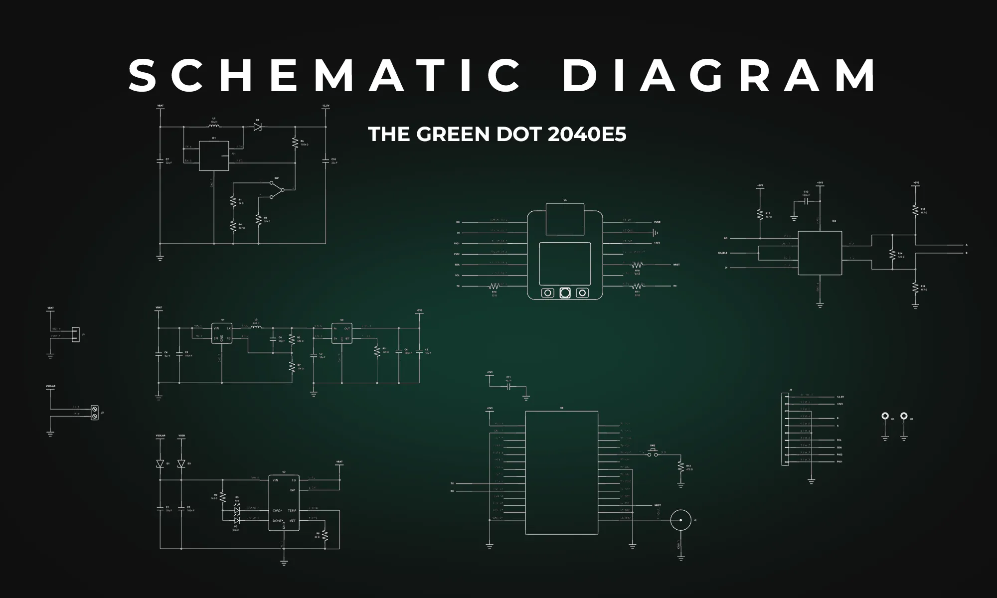
Explore the essentials of schematic diagrams in our comprehensive guide, covering everything from basic resistors to complex integrated circuits, and learn to master the visual language of electronics.
A schematic diagram abstracts the complexity of an electrical circuit into a more digestible form, using standardized symbols to represent various components like capacitors, diodes, and logic gates. These diagrams function as the visual language of electronics, allowing engineers to communicate intricate circuit details efficiently. Without a well-designed schematic, even the most brilliant circuit ideas risk becoming an impractical jumble of components.
All components have their own designators and symbols that help schematic designs define the interconnections of their electric circuit.
The mastery of schematic diagrams is more than a mere technical skill; it's a vital competency that can make or break your designs. The intricacies of each symbol, from the humble resistor to complex integrated circuits, combine to form the language of electronics. Fluent communication in this language enables you to translate creative concepts into functional, reliable circuits. By investing in a deeper understanding of each component and its schematic representations, you position yourself for more insightful design, efficient problem-solving, and ultimately, better-engineered solutions.
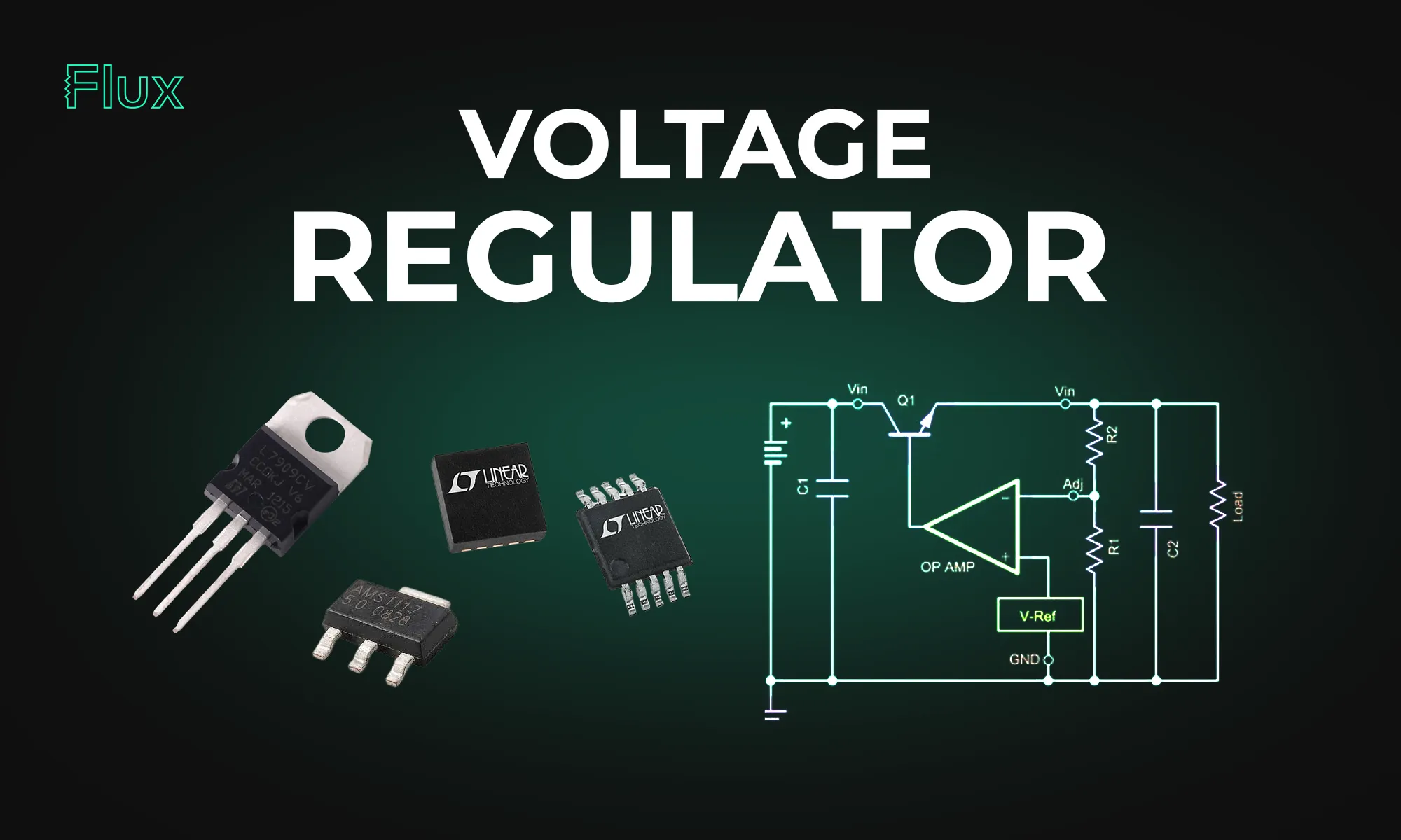
This blog post explores the diverse mechanisms and applications of voltage regulators, highlighting their significance in maintaining stable voltages in everything from basic electronic circuits to complex systems.
Voltage regulation mechanisms vary, but all share the goal of mitigating voltage drop and maintaining a steady voltage output. Zener diodes, for instance, exploit the property of reverse breakdown voltage to provide a reference voltage or to protect circuits from voltage spikes. Transistors, such as bipolar junction transistors (BJTs), are employed in more complex regulator designs, where their ability to act as variable resistors is used to adjust the output voltage dynamically.
Zener diodes are a straightforward solution for voltage regulation. When reverse-biased, a Zener diode allows current to flow once the voltage drop across it exceeds the Zener voltage, maintaining a nearly constant voltage over a wide range of currents. This makes it an ideal component for creating a reference voltage or for small-scale voltage regulation tasks.
Transistors such as BJTs are used in active voltage regulators. They can amplify or switch electronic signals, making them versatile components in various voltage regulator configurations. In a common emitter configuration, for example, the base-emitter voltage is used to control the output voltage, providing precise regulation capabilities.
Buck boost converters are types of switch-mode power supplies that can step up (boost) or step down (buck) an input voltage. These converters use a combination of inductors, diodes, and capacitors, alongside a switching element like a transistor, to control the transfer of energy and thus regulate the voltage.
A buck converter, or step-down regulator, reduces the input DC voltage to a lower output voltage. It operates by rapidly switching the transistor on and off, controlling the time the voltage is applied to an inductor. The energy stored in the inductor is then released at the desired lower voltage.
Conversely, a boost converter steps up the input voltage to a higher level. It uses similar principles as the buck converter but arranges the components differently to increase the voltage during the off phases of the switching cycle.

The 78xx series regulators are integrated circuits designed to provide a fixed output voltage with a high degree of stability. The "xx" in 78xx indicates the output voltage the regulator is designed to provide, making these components easily identifiable and user-friendly.
The 78xx series offers ease of use, with built-in features like thermal overload protection, short-circuit protection, and safe area protection. These regulators are favored in applications where a simple, robust voltage regulation solution is required without the complexity of external components.
A voltage divider is a passive circuit that uses two resistors to reduce a voltage to a required level. While this method is simple and cost-effective, it is not typically used for regulation, as the voltage drop across the resistors changes with the current draw, making it unsuitable for dynamic loads.
Voltage dividers are inherently inefficient for voltage regulation due to their sensitivity to load variations. The voltage drop across the resistors can lead to substantial power loss, especially when regulating high voltages to much lower levels.
Designing an effective voltage regulator circuit requires a comprehensive understanding of the load requirements, voltage levels, and the potential for voltage drop in the system. Selecting the appropriate regulator—whether it be a Zener diode for simple tasks, a transistor-based regulator for more demanding applications, or an integrated solution like the 78xx for fixed outputs—is crucial.
For transistor-based regulators, calculations must account for the transistor's characteristics, such as its current gain and saturation voltage. In contrast, integrated regulators like the 78xx series require minimal external components, simplifying the design process.
Voltage regulation technology must address several challenges, including efficiency, heat dissipation, and response to changing loads or supply variations.
Efficiency is a primary concern in voltage regulators, especially in systems where power loss translates into unwanted heat. Heat sinks and thermal management strategies are critical in high-power applications to prevent overheating and ensure reliable operation.
A voltage regulator must respond quickly to changes in load or supply voltage to maintain stable voltage. Switch-mode regulators like buck and boost converters excel in this regard, offering fast response times and high efficiency.
Voltage regulation is an indispensable function in electronic systems, ensuring that sensitive components receive the correct operating voltage. From simple Zener diodes to sophisticated integrated circuits like the 78xx series, voltage regulators provide the stability required for today's electronic devices to operate reliably. Understanding the principles of voltage regulation, the various types of regulators available, and the challenges involved in their design and implementation is crucial for any electrical engineer or technician working in the field. Whether stepping down voltage in a buck converter, managing voltage drop with resistors, or employing a Zener diode for basic regulation tasks, these components form the backbone of stable and reliable electronic circuitry.
Dive into the world of DIY Arduino projects, learning everything from choosing the right board to creating advanced home automation systems.
Arduino offers a variety of board options to cater to different project needs, varying in size, input/output capabilities, and specifications. The most commonly used ones include:
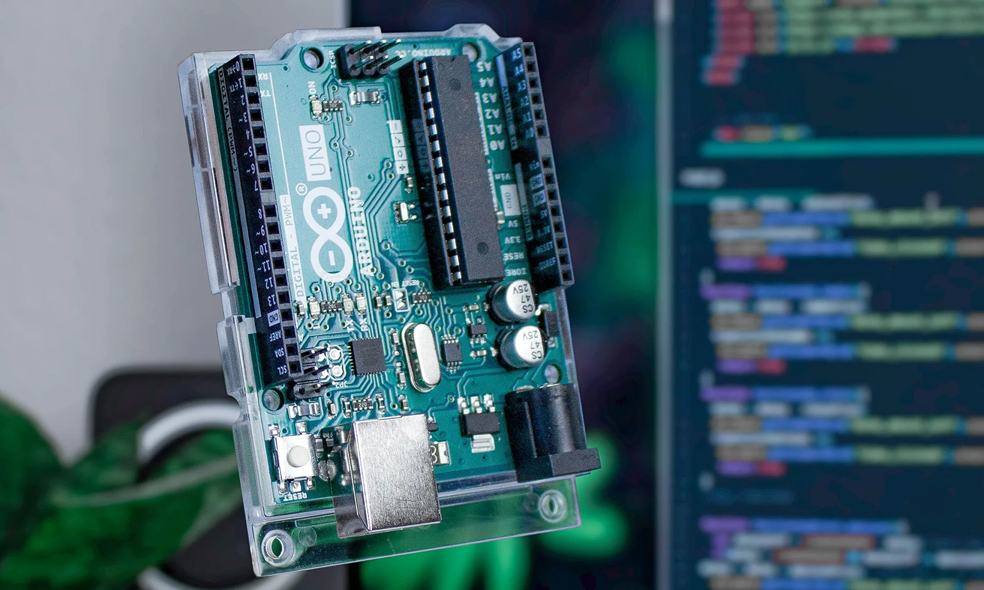
The Arduino Uno is often the starting point for beginners, and it's crucial to understand its technical specifications. This remarkable board is equipped with the ATmega328P microcontroller, based on the AVR architecture. The ATmega328P boasts 32 KB of flash memory for program storage, 2 KB of SRAM for data storage, and 1 KB of EEPROM for non-volatile storage. With 14 digital input/output pins, six analog inputs, and a 16 MHz quartz crystal, the Arduino Uno offers a rich set of features for your projects.
When your project demands more processing power and an abundance of I/O pins, the Arduino Mega steps in. It features the ATmega2560 microcontroller, offering a substantial 256 KB of flash memory, 8 KB of SRAM, and 4 KB of EEPROM. With a whopping 54 digital input/output pins and 16 analog inputs, the Mega is perfect for complex and resource-intensive applications. Whether you're working on 3D printers, robotics, or other large-scale projects, the Arduino Mega has you covered.
For projects where size is a critical factor, the Arduino Nano shines. It's a compact board that doesn't compromise on capability. The Nano is powered by the ATmega328P, like the Uno, and includes 32 KB of flash memory, 2 KB of SRAM, and 1 KB of EEPROM. It offers 22 digital input/output pins and 8 analog inputs, making it an excellent choice for compact and portable projects. From wearables to small IoT devices, the Arduino Nano's small footprint is an advantage.
To kickstart your journey into Arduino projects, you need to familiarize yourself with some fundamental concepts and components. Here are the key players in the world of Arduino:
To create, upload, and run code on your Arduino, you'll need the Arduino IDE (Integrated Development Environment). This intuitive software streamlines the programming process, enabling you to write and upload code effortlessly. If you haven't already, download and install the Arduino IDE from the official Arduino website.
Now that you've got the basics down, it's time to explore a few Arduino project ideas to inspire your journey into DIY electronics. We'll start with some straightforward projects and gradually progress to more advanced ones.
The LED blink project is the Arduino equivalent of 'Hello World.' It's the perfect introduction to the Arduino platform, helping you understand the basics of code compilation and uploading. Using a breadboard, connect an LED to one of the digital pins, and use a simple code snippet to control it. Here's an example Arduino sketch to blink an LED connected to digital pin 13:
In this code, we set pin 13 as an output and alternate between turning the LED on and off with one-second delays.
Unlock the power of Arduino by utilizing a temperature sensor to create a project that provides real-time temperature readings. The DHT22 temperature sensor is an excellent choice for measuring ambient temperature and humidity accurately. Display the collected data on an LCD screen for easy visualization.
Technical Insights:
For those with a passion for gardening, Arduino offers the opportunity to build a smart plant watering system. Two distinct approaches are possible:
Arduino empowers you to transform your home into a smart living space, offering precise control over various aspects of your environment. By leveraging an Arduino and an array of sensors, Wi-Fi modules, and relay controls, you can enhance convenience, safety, and energy efficiency.
Technical Insights:
Arduino opens the door to creating intricate robotic systems, and a Bluetooth-controlled robot is an excellent example. This project seamlessly integrates motors, sensors, and Bluetooth modules for smartphone control, offering an educational experience in motor control.
Technical Insights:
As you engage in more complex Arduino projects, you might encounter technical challenges. Here are some advanced troubleshooting tips:
As you pursue your journey of Arduino projects, keep in mind that there's a diverse range of peripherals you can use to add functionality and interactivity to your creations. Here are some noteworthy accessories to consider:
By incorporating these components and exploring a wider array of project ideas, you'll gain a deeper understanding of Arduino's versatility and its potential for innovation. So, let your creativity flow and embark on a journey of endless possibilities with Arduino.
Explore the world of Arduino with a step-by-step guide on writing your first code and setting up a fundamental 'Blink' project to bring electronics to life.
Let's first grasp the foundational concepts of Arduino. At its core, Arduino is a microcontroller-based platform designed to facilitate the development of electronic projects. Like the popular Arduino Uno boasting an atmega328p microchip, a microcontroller is a compact computing device specifically engineered to perform dedicated tasks.

Arduino revolves around writing and executing code to bring your creations to life. So, let's check out the technicalities of Arduino code and understand how it functions.
The Arduino IDE, or Integrated Development Environment, is your primary workspace for crafting Arduino code. This environment offers a user-friendly interface that streamlines the process of writing, verifying, and uploading code to your Arduino board. Let's dissect the core components of the Arduino IDE:
Today we'll create a straightforward "Hello, Arduino!" program employing the void setup() and void loop() functions.
When it comes to Arduino code, you'll frequently encounter the term "void." In the below context, "void" indicates that a particular function doesn't return any values. It's worth noting that "setup()" and "loop()" are fixed names for functions in Arduino code. The "setup()" function is where you initialize variables, and it runs once when the board powers up. The "loop()" function, on the other hand, is the core of your program, running repeatedly to control your project.
Let's break down the technical aspects of this code:
The quintessential "Blink" project is Arduino's equivalent to "Hello, World!" in the programming universe. It's a basic exercise involving the toggling of an LED. In this project, an LED connected to digital pin 13 blinks on and off at one-second intervals. We've already written the code for this above, so now let's see how we can apply it.
Connect the components as follows:
With your components interconnected, apply and upload the code written above to set the LED blinking!
As you continue your journey into the captivating realm of Arduino code, it's essential to broaden your understanding of some fundamental concepts and explore the wealth of tools at your disposal.
The Power of Functions
Functions are the backbone of Arduino programming. We've already used a couple, but let's talk about functions in general. Functions are reusable blocks of code designed to perform specific tasks. Each function has a name, a set of parameters it can accept, and a return type, which specifies the data it provides after executing.
Functions facilitate modularity, making your code more organized and easier to maintain. Here are some key concepts to grasp:
Exploring Libraries: A World of Connectivity and Creativity
Libraries are the secret sauce that amplifies Arduino's capabilities. They are pre-written code modules that extend the functionality of your Arduino board. Let's touch upon a few libraries that can serve as inspiration for your projects:
Some Interesting Advanced Functions
To spark your creativity and inspire your journey, here are a few advanced functions and ideas:
As you set forth on your journey as a digitalwriter in the Arduino universe, remember that practice and experimentation are your allies. Embrace the rich array of functions and libraries at your disposal. Seize your Arduino, commence coding, and unleash the infinite potential residing within your creative ideas!