Today, we’re excited to share our Summer Update to Flux AI Auto‑Layout, a collection of improvements designed to make one‑click PCB routing more reliable, transparent, and adaptable to your real‑world workflows.
Learn how smart vias in Flux automates the selection, placement, and configuration of vias during the PCB design process. This automation reduces the manual effort involved in via placement and significantly lowers the risk of misalignment and other common errors associated with traditional via management.
Even for the most experienced engineers, high density interconnect designs remain difficult. Some typical challenges are:
Traditional EDA tools depend heavily on manual input for via placement. This makes density management primarily a function of hand-eye coordination. After placement, when you need to modify part of the design, you’ll quickly find yourself playing an unsolicited game of three-dimensional chess. Often, it’s easiest to simply wipe out the traces and vias, start over, and hope you won’t have to make another change to that part of your board.
After carefully laying everything out, the next big effort is to define and work through manufacturability, reliability, and cost considerations. In practice, this mountain of manual labor adds up. Designers are often forced to either compromise their design, risk overlooking mistakes, or delay their project.
Smart Vias in Flux is an intelligent feature that automates the selection, placement, and configuration of vias during the PCB design process. This automation reduces the manual effort involved in via placement and significantly lowers the risk of misalignment and other common errors associated with traditional via management
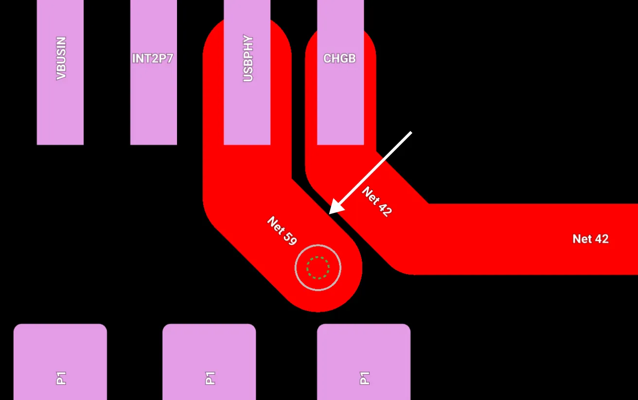
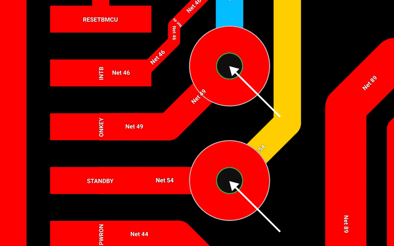
If you’re routing a trace and need to connect across multiple layers, Flux will place a Smart Via that automatically populates with the best suited combination of vias (micro, blind, buried, or through-hole), in a stacked or staggered configuration, respecting your project settings. For example, you might only want to use microvias on outer layers and use through-hole vias for everything else. With Smart Vias, you can just start routing. When you switch from Top to Mid-Layer 1, a Smart Via will get you there. You can change your mind and go to Bottom and the Smart Via will dynamically reconfigure itself to support that connectivity.

Smart Vias are powered by Flux’s innovative Layout Rules. Rules allow you to set your preferences from a central place in the Stackup. They also allow for control of individual Smart Vias right down to the details, like the direction or spacing of a stagger. The result is a feature gets out of your way when you want and also lets you sweat the small stuff.
To make it even easier to get started, simply clone or fork any of these templates.
Overall, Smart Vias addresses many of the challenges inherent in high density interconnect design and offers notable benefits to the designer.
We think this is a huge improvement over existing workflows and we’re excited for you to use it. Interested in experiencing the new Smart Via feature? Get started with a template today!
Avoid costly errors in your PCB design with these expert tips! Discover the 5 most common mistakes in trace width, vias, power planes, and more. Learn how Flux’s AI Copilot helps you catch these issues early, ensuring your board is ready for manufacturing.
Let's dive in.
One of the most common mistakes in PCB design is not paying enough attention to trace width and spacing, especially in high-current or high-speed applications. If the trace is meant to carry high currents but it happens to be too narrow, it can result in thermal issues or even a failure of the circuit.
The width of your trace can be determined by things like; how much current it should carry without overheating or causing excessive voltage drops, Impedance control, and sensitivity of the signal running through it.
Flux makes routing high speed signals, such as USB data lines, easier by automatically performing coupled routing of the data lines (D+ and D-) and calculating the impedance of the pair based on the PCB stackup. This helps prevent reflections that can cause signal distortion, timing issues, and data corruption.
Flux Copilot can also help you calculate the appropriate trace width based on the current it needs to carry, while also considering the required impedance for high-speed signals. Just ask something like:
@copilot please recommend trace width for my VBUS.
Then copilot responses:
“For VBUS, typically a 5V supply in USB applications, let's assume a common scenario where you might anticipate a current of up to 1A. Using a temperature rise of 10°C, the general guideline for trace width on a 1 oz/ft² copper PCB is approximately 20-30 mils (0.5-0.8 mm) per amp of current.”
Vias are crucial for connecting different layers in a PCB, but choosing the wrong size or type can cause issues in both signal integrity and manufacturing. Blind, buried, and microvias are often used in high-density interconnect (HDI) boards, but these require careful consideration during design. For instance, microvias are perfect for compact designs, but if placed improperly, they can lead to poor layer transitions or increased inductance.
Flux let’s you set up your stackup where you add all the manufacturer capabilities. When you need some more advice on what stackup best suits your design, always feel free to ask copilot for some ideas, you could ask
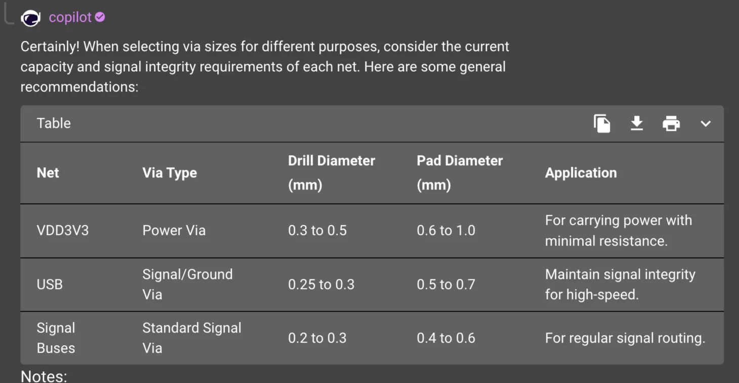
@copilot in a table format recommend vias sizes that i can use for my VDD3V3, my USB, and the other signal buses?
Then here's the copilot response,
If you're routing a high-speed differential pair, such as USB or PCIe, through multiple layers, via stubs can cause signal reflections that degrade signal quality. A rule of thumb is to ensure via lengths are minimized, or even better, use back-drilling techniques to remove stubs, especially in high-frequency circuits.
Moreover, not all manufacturers support the same via sizes, so checking with your manufacturer early in the design process can avoid headaches later. Make sure to adhere to their capabilities, including the aspect ratio limits (via depth to diameter), to avoid costly redesigns e.g. 20:1 for PCBWay.
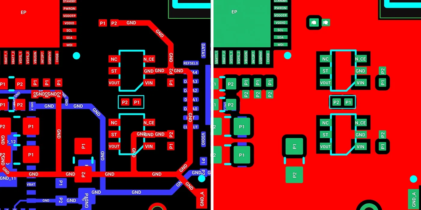
The layout of power and ground planes is another common area where mistakes are made. These planes act as the backbone of your circuit's stability, so a poorly designed plane can introduce noise, increase EMI, and degrade power delivery.
By default, Flux starts you off with a solid, contiguous ground plane since it is critical for minimizing noise and providing a low-impedance return path for high-speed signals. It is advisable to avoid creating islands which can cause severe signal integrity.
Example:
Imagine routing a high-speed signal across a split ground plane. The signal may cross the gap, creating a longer return path, which increases inductance and can lead to signal distortion or timing errors in critical circuits like clocks or data buses.
Similarly, power planes should be wide enough to handle the current required by each section of the circuit. For designs with sensitive analog circuits, it’s often a good idea to have separate power planes or split planes for analog and digital sections to avoid cross-talk and noise coupling.
Designing with manufacturability in mind is essential to ensure that your board can be built without issues. It’s easy to forget that the design rules you use in your ECAD tool may not fully align with your manufacturer’s capabilities, and this can result in delays or additional costs.
Flux provides users with pre-configured templates which align with most of the popular manufacture (e.g. PCBWay, JLCPCB, AISLER, LION Circuits, SEEED Studio and many more) capabilities so that users don’t have to worry about manually configuring things like trace widths, keepout, and other parameters. A good general rule of thumb is to always start new project using Flux manufacturer design rule templates
There are numerous DFM tips but here are some common ones to consider;
Using Flux manufacturer design rule templates will alert you when either of the manufacturer capabilities are violated even before sending your files for manufacturing saving you time.
Decoupling capacitors are used to filter out noise and provide a stable voltage to ICs, especially in digital circuits where rapid switching causes power fluctuations. However, placing these capacitors too far from the pins of the IC can render them ineffective. It is advisable to place these decoupling capacitors as close as possible to the IC without violating the minimum spacing a manufacturer can work with.
Example:
In a typical microcontroller design, you should place decoupling capacitors (such as 0.1µF and 1µF) as close as possible to the VCC and GND pins. Ideally, the capacitors should be placed on the same layer as the IC to reduce parasitic inductance and ensure faster response times. Failure to do so can cause power integrity issues, leading to glitches or resets in your circuit.
Additionally, use vias sparingly when routing decoupling capacitors. Each via adds inductance to the path, which reduces the capacitor's ability to suppress high-frequency noise.
Before pressing that button to send your PCB design for manufacturing, it's worth taking a step back and performing a thorough review of your design. These design review steps can be quite a handful but what we have discussed above can be considered as the bare minimum. Flux manufacturer design rules makes it easy to ensure trace widths, appropriate via sizes, and manufacturer capabilities are considered when designing your board.
A thorough PCB design review can be a very daunting task, you might not be sure where to start or what checks to include in the review process. That is one of the reasons Flux’s AI lives in your project. You can use copilot to quickly check decoupling capacitors, power and grounding, ensuring compliance with industry standards, and even creating a stronger supply chain. To learn more about how you can use this tool, Sign up for Flux today.
Learn about STM32 microcontrollers, popular series, USB OTG, SWD, UART, and development tools. Find the right STM32 MCU and kickstart your projects.
A typical microcontroller includes a processor, memory and Input/Output (I/O) peripherals on a single chip. Its components may be extended to include: Digital I/O, Analog I/O, Timers, Communication interfaces, Watchdog (a timer that is responsible for the detection of timed out or locked instruction).
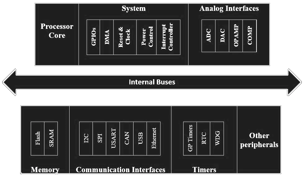
A processor is a little chip present in the device that has the role of arranging the instructions and order the outputs. The manufacturer defines the integrated peripherals and the hardware capabilities.
STM32 microcontrollers are divided into several groups based on their target applications. Below is a quick overview to help you choose the right MCU series:
{{insert-project-1-here}}
There are two ways to use an STM32 MCU which are:
{{insert-project-2-here}}
STM32 microcontrollers come equipped with several critical features that make development smoother, especially for embedded applications. Here are a few that stand out:
{{insert-project-3-here}}
To get started with STM32, you’ll need a development board. Here are some of the top picks, whether you’re on a budget or seeking advanced features:
Once you’ve chosen a development board, the next step is setting up the software. Below are some of the best free IDEs and tools to get started with STM32 programming:
For IoT projects, consider Arm Mbed, a platform that supports cloud-based development and is optimized for low-power devices.
STM32CubeMX simplifies the configuration process by generating initialization code. You can:
Create a basic “blinky” program to blink an LED. This is a great way to ensure everything is set up correctly.
{{insert-mark-video}}
You can find STM32 MCUs and development boards from trusted vendors, such as:
STM32 microcontrollers are an excellent choice for both beginners and advanced developers. They offer a wide range of features, low power consumption, and support for IoT, wireless communication, and industrial automation. With STM32Cube tools and free IDEs, you can build your projects faster and more efficiently.
Whether you’re working on a simple blinky LED project or a complex IoT solution, STM32 has the right series to fit your needs. Get your development board, set up your environment, and start building today!
Q: What is the best STM32 series for beginners?
A: The STM32F1 and STM32F4 series are great starting points, as they are well-documented and widely supported.
Q: Is STM32CubeIDE free?
A: Yes, STM32CubeIDE is free and available for Windows, macOS, and Linux.
Q: How much does an STM32 microcontroller cost?
A: Prices vary by series, with the STM32F1 starting around $2 and high-end STM32H7 costing up to $30.
Q: Is STM32 better than Arduino?
A: While Arduino is simpler and more beginner-friendly, STM32 offers more power, flexibility, and scalability. STM32 microcontrollers provide better performance with faster processing speeds, more peripherals, and lower power consumption, making them ideal for more advanced or professional projects. On the other hand, Arduino is great for quick prototyping and those new to microcontrollers.
Q: What are STM32 microcontrollers used for?
A: STM32 MCUs are used in a wide range of applications, including IoT devices, automotive systems, industrial automation, wearables, and smart home products. Their versatility makes them suitable for both high-performance tasks (like multimedia processing) and low-power applications (like battery-operated devices).
Looking for a comprehensive guide to ESP8266 pinout? Check out our article that covers everything you need to know about the ESP8266's pins, including digital, analog, and PWM pins. Perfect for beginners and experts alike, our guide will help you understand the ESP8266's pinout and how to use it in your projects.
In this guide, we’ll walk through:
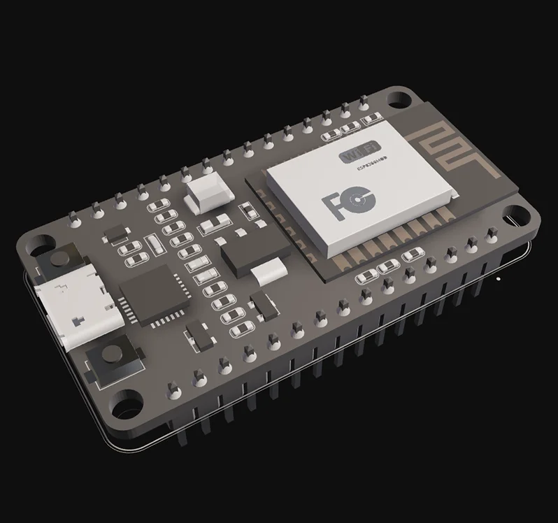
The ESP8266 is a low-cost Wi-Fi microcontroller by Espressif. It enables wireless IoT projects without needing a separate Wi-Fi module. Popular boards like the NodeMCU and Wemos D1 Mini use it as their core.
The ESP8266 microcontroller module features a total of 32 pins, each with a function that contributes to its remarkable utility. Here, we'll break down these key specifications to provide a clear understanding of its pinout:
The ESP8266 features 32 pins, but not all are usable for general I/O. Here’s a breakdown:
You can power ESP8266 directly via the USB connector (standard USB = 5V) or the Vin pin (5V to 10V). The regulator provides a maximum of 500mA.
These are the power pins of this microcontroller board:
It's essential to realize that the GPIO labeling on the ESP8266 does not correspond directly to the silkscreen markings on the board. For instance, the pin marked as D0 is actually GPIO16, while the one labeled D1 is in fact GPIO5.
The table below outlines the relationship between the silkscreen labels on the board and the actual GPIO numbers, detailing the most suitable pins for your projects and highlighting those that require careful handling.
GPIO6 to GPIO11 are usually connected to the flash chip in ESP8266 boards. So, these pins are not recommended to use.
The ESP8266 can be prevented from booting if some pins are pulled LOW or HIGH. The following list shows the state of the following pins during BOOT:
{{insert-project-1-here}}
ESP8266 only has one analog input, it's the ADC0 pin, usually labelled as A0 on the board. If you're using the bare ESP8266 chip, the maximum input voltage range of this ADC0 is 0 to 1V, for development board like NodeMCU ESP8266 12-E, the voltage input range is 0 to 3.3V due to presence of internal voltage divider.
This ADC pin has a 10-bit resolution, which means you’ll get values between 0 and 1023.
Unlike other microcontrollers, the ESP8266 lacks dedicated hardware for I2C; however, I2C functionality can be implemented in software, allowing any GPIOs to be used for I2C purposes. Commonly, the following GPIOs are used as I2C pins:
The pins used as SPI in the ESP8266 are:
The ESP8266 supports interrupts in any GPIO, except GPIO16.
The GPIO pins on the esp8266 are the backbone of its versatility, allowing you to connect various components to create a wide array of IoT applications. To illustrate their practical utility, let's consider a simple project: building a weather monitoring station.
And with the many additional pinouts, our weather monitoring station can always be improved--add a temperature sensor to GPIO2, or a humidity sensor to GPIO3!
{{insert-project-2-here}}
The esp8266 pinout is also perfect for developers who are already comfortable with the Arduino IDE, as they seamlessly integrate, making the esp8266 widely accessible.
Using the Arduino IDE with the esp8266 offers several benefits:

When it comes to practical application, the Wemos D1 Mini, built around the esp8266, is a favorite among developers. Its compact size, affordability, and extensive support from the maker community have made it a go-to choice for IoT projects.
Here are some reasons why the Wemos D1 Mini is an excellent choice:
In the evolving landscape of IoT, the esp8266 pinout is highly versatile. Its GPIO pins, compatibility with Arduino IDE, I2C capabilities, and integration into popular development boards like the Wemos D1 Mini provide a robust foundation for your IoT projects. However, if you're looking for something more, then check out its sibling, the esp32. The esp32 retains the flexibility of the esp8266 pinout while offering more processing power, built-in Bluetooth, and dual-core processing. This opens up new opportunities for more complex and feature-rich IoT applications.
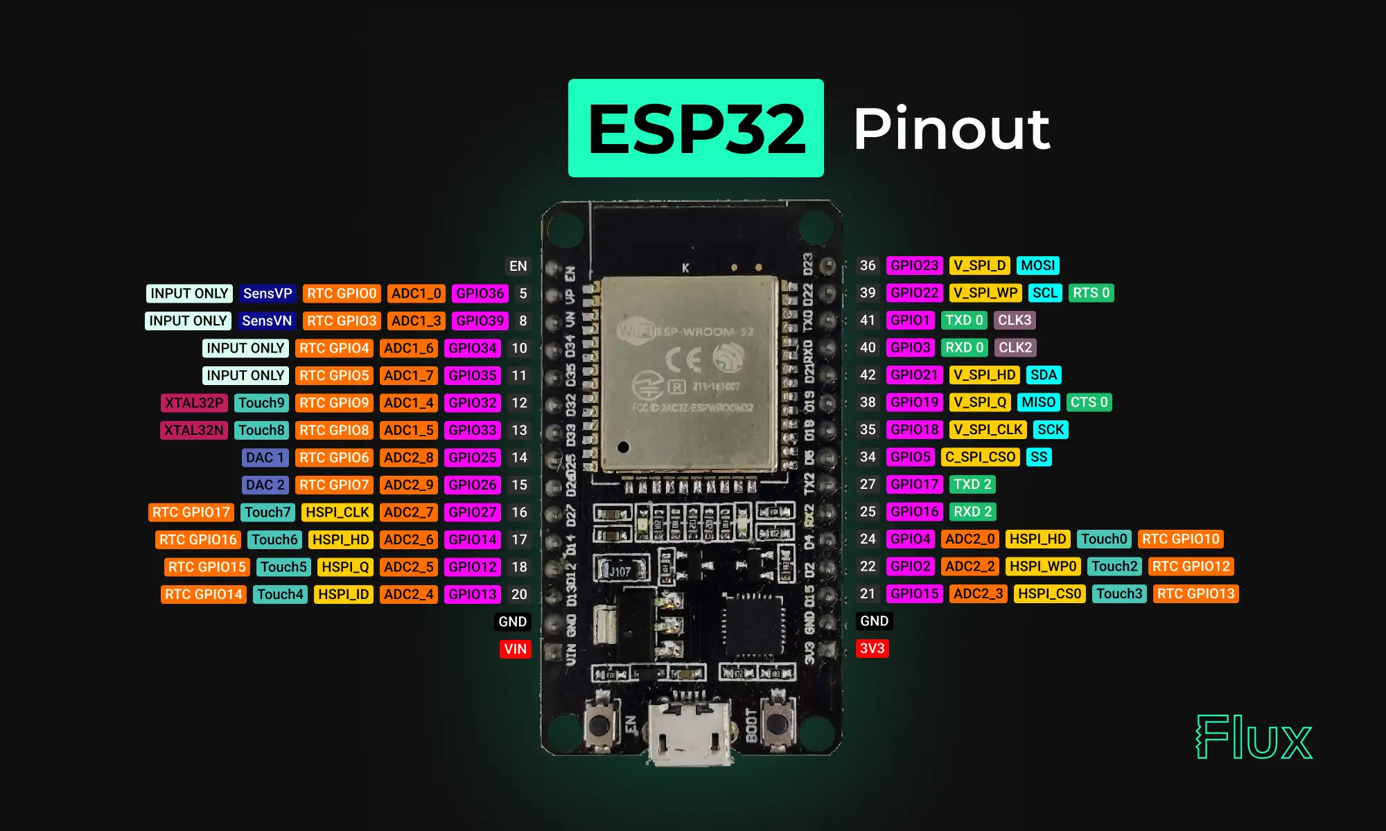
Looking for a comprehensive guide to ESP32 pinout? Check out our article that covers everything you need to know about the ESP32's pins, including digital, analog, PWM, and Strapping pins. Perfect for beginners and experts alike, our guide will help you understand the ESP32's pinout and how to use it in your projects.
Yes, the ESP32 has digital pins, also known as General Purpose Input/Output (GPIO) pins. These pins are used for digital input and output and can be configured as either inputs or outputs depending on the needs of the project. The ESP32 has a total of 36 GPIO pins that can be used for various purposes, including interfacing with sensors, controlling LEDs, and communicating with other devices.
NOTE: not all GPIOs are accessible in all development boards, but each specific GPIO works in the same way regardless of the development board you’re using. For ESP32 DEVKIT V1 board, GPIO6 to GPIO11 are connected to the integrated SPI flash and are not recommended for other uses.
The ESP32 is a 3.3V device, which means that all of its input and output pins are designed to operate with a maximum voltage of 3.3 volts. Connecting the ESP32 to a voltage source greater than 3.3 volts can damage the device, so it's important to use level shifters or voltage dividers when interfacing with higher voltage devices.
It's also important to note that the power supply for the ESP32 should be 3.3V DC. Some development boards or modules may have built-in voltage regulators that can accept a higher input voltage (such as 5V) and regulate it down to 3.3V for the ESP32, but it's always best to check the specifications of the specific device you are using to ensure proper voltage supply.
These pins don’t have internal pull-up or pull-down resistors. They can’t be used as outputs, so use these pins only as inputs:
To utilize these pins in Arduino IDE, and you want to make GPIO 22 as input and GPIO 23 as output:
{{insert-project-1-here}}
pinMode() configures the specified pin to behave either as an input (with or without an internal weak pull-up or pull-down resistor), or an output. It is possible to enable the internal pullup resistors with the mode INPUT_PULLUP. Additionally, the INPUT mode explicitly disables the internal pullups.
There are three serial ports on the ESP32 known as U0UXD, U1UXD and U2UXD all work at 3.3V TTL Level. There are three hardware supported serial interfaces on the ESP32 known as UART0, UART1 and UART2. Like all peripherals, the pins for the UARTs can be logically mapped to any of the available pins on the ESP32. However, the UARTs can also have direct access which marginally improves performance. The pin mapping table for this hardware assistance is as follows.
Strapping pins are used to put the ESP32 into bootloader or flashing mode. On most development boards with built-in USB to SERIAL, you don't need to worry about the state of these pins. The board itself puts the pins in the right state prior to flashing or when on boot mode.
Some GPIOs change their state to HIGH or output PWM signals at boot or reset. This means that if you have outputs connected to these GPIOs you may get unexpected results when the ESP32 resets or boots.
NOTE: If you have peripherals connected to these pins, you may encounter issues with trying to upload new code, flashing the ESP32 with new firmware, or resetting the board, it may be because those peripherals are preventing the ESP32 from entering the right mode.
{{insert-nico-video}}
The ESP32 has two I2C channels and any pin can be set as SDA or SCL. When using the ESP32 with the Arduino IDE, the default I2C pins are:
You can use the wire library to use other pins for I2C, you just need to call:
These are the default pin mapping for SPI
GPIO 6 to GPIO 11 are exposed in some ESP32 development boards. However, these pins are connected to the integrated SPI flash on the ESP-WROOM-32 chip and are not recommended for other uses. So, don’t use these pins in your projects:
{{insert-project-2-here}}
Goodnews. All ESP32 GPIO pins are interrupt-capable (interrupts) pins. You can enable the interrupt functionality to any GPIO input pin using this function from the Arduino Core.
Enable (EN) is the 3.3V regulator’s enable pin. It’s pulled up, so connect to ground to disable the 3.3V regulator. This means that you can use this pin connected to a pushbutton to restart your ESP32, for example.
The ESP32 has built-in Analog to Digital Converters (ADC) that allow it to convert analog signals into digital values that can be processed by the digital circuits on the chip. The ESP32 has a total of 18 ADC channels, which can be used to read analog signals from various sensors, such as temperature sensors, light sensors, and other types of sensors that output analog signals.
The ESP32's ADC has a resolution of 12 bits, which means that it can measure the analog signal and convert it into a digital value between 0 and 4095. The ADC can also be configured to sample the analog signal at different rates and can be programmed to read multiple channels simultaneously.
The ESP32 has 18 x 12 bits ADC input channels (while the ESP8266 only has 1x 10 bits ADC). These are the GPIOs that can be used as ADC and respective channels:
There are 2 x 8 bits DAC channels on the ESP32 to convert digital signals into analog voltage signal outputs. These are the DAC channels:
The ESP32 has 10 capacitive touch GPIOs. These GPIOs can sense variations in anything that holds an electrical charge, like the human skin. So they can detect variations induced when touching the GPIOs with a finger.
These pins can be easily integrated into capacitive pads, and replace mechanical buttons. Additionally, the touch pins can also be used as a wake up source when the ESP32 is in deep sleep.
To use the ESP32 touch sensor in Arduino:
Reading the touch sensor is straightforward. You use the touchRead() function, that accepts as argument, the GPIO you want to read.
This example arduino sketch reads the touch pin 0 and displays the results in the Serial Monitor.
{{insert-project-3-here}}
There is RTC GPIO support on the ESP32. The GPIOs routed to the RTC low-power subsystem can be used when the ESP32 is in deep sleep. These RTC GPIOs can be used to wake up the ESP32 from deep sleep when the Ultra Low Power (ULP) co-processor is running. The following GPIOs can be used as an external wake up source.
The ESP32 pulse width modulation PWM controller has 16 independent channels that can configured to generate PWM signals with different configuration and properties that can be used for controlling the intensity of digital signals, such as LEDs and Motors. PWM is a technique that allows the duty cycle of a digital signal to be varied, which in turn changes the average voltage and current delivered to the load.
The PWM frequency can be set using the ledcSetup() and ledcAttachPin() functions, which allow you to configure the PWM frequency and attach the PWM pin to a specific output.
In addition to the 16 hardware PWM pins, the ESP32 also supports software-based PWM, which can be used to control additional PWM channels on any GPIO pin. The ESP32's software PWM uses a technique called bit-banging, which allows the duty cycle of a digital signal to be varied by software.
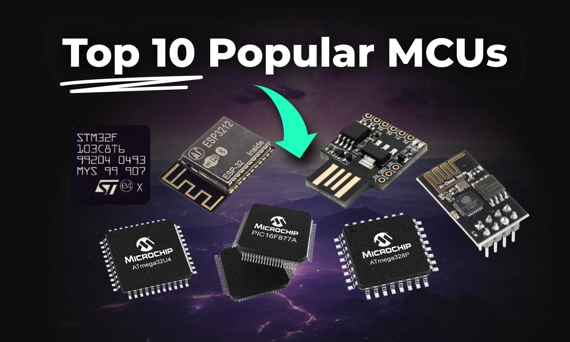
This article highlights 10 of the most popular microcontrollers, based on their usage in embedded systems, memory architecture, and the community support they enjoy.
This article highlights 10 of the most popular microcontrollers, based on their usage in embedded systems, memory architecture, and the community support they enjoy. Let’s dive in!
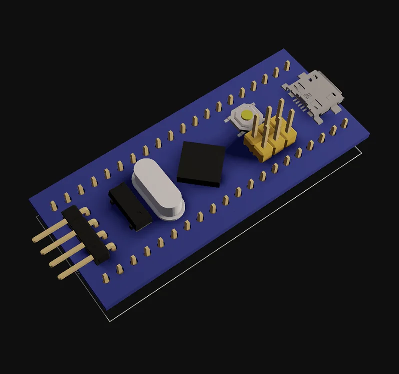
The STM32F103C8T6 is a versatile microcontroller with a 32-bit ARM Cortex-M3 core running at 72 MHz. It offers flash memory, non-volatile memory, and multiple peripherals like SPI, I²C, and CAN. Its performance makes it ideal for general-purpose embedded systems.
Key Features:
Development Board:
The ATmega328P, a popular Atmel microcontroller, powers many Arduino boards like the Uno. It offers easy programming through the Arduino IDE and features EEPROM for non-volatile memory storage. This microcontroller is great for beginners and general-purpose applications.
Key Features:
Development Boards:
The PIC16F877A is a Microchip microcontroller widely used for educational purposes. Its support for non-volatile memory and easy-to-use peripherals makes it an excellent choice for beginners.
Key Features:
Development Board:
The ATtiny85, another compact Atmel microcontroller, is ideal for small embedded systems. It supports SPI, I²C, and offers EEPROM for non-volatile memory.
Key Features:
Attiny85 ready-to-use module:
Development Boards:
The MSP430G2452 from Texas Instruments is known for low power operation, making it ideal for battery-powered embedded systems. It features essential peripherals and non-volatile memory.
Key Features:
Development Board:
The ESP8266, a Microchip microcontroller, offers Wi-Fi connectivity and supports UART and SPI peripherals. It’s ideal for IoT projects and wireless applications.
Key Features:
Development Boards:
The ESP32 builds on the ESP8266 by adding dual-core processing and Bluetooth support. It is a powerful microcontroller for advanced embedded systems and general-purpose applications.
Key Features:
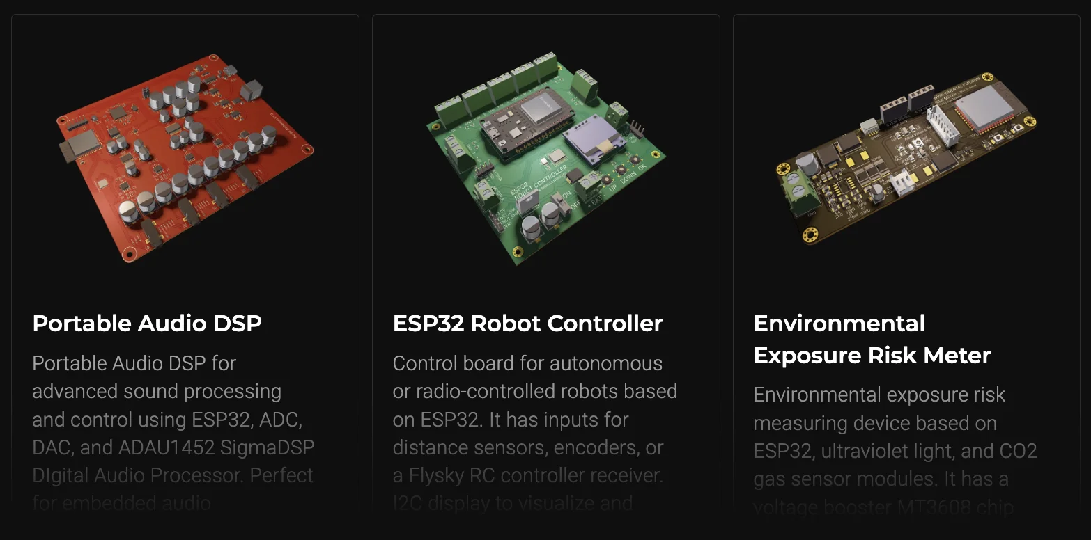
Curious about what you can build with the powerful ESP32 microcontroller? From smart home devices to IoT-based monitoring systems, the possibilities are endless! Check out some incredible ESP32 featured projects created by the Flux community, and get inspired to build your own.
Development Boards:
The ATmega32U4, another Atmel microcontroller, supports USB connectivity. It’s commonly used in custom keyboards and other embedded systems requiring serial communication.
Key Features:
Development Boards:
The STM8S103F3 is a reliable 8-bit microcontroller for industrial automation. It offers robust peripherals for control systems.
Key Features:
Development Boards:
The LPC1768 is a high-performance microcontroller with advanced connectivity peripherals like Ethernet and USB. It is suitable for demanding embedded systems.
Key Features:
Development Boards:
Every microcontroller listed here offers unique features for embedded systems. If you need low power operation, like the MSP430, or the wireless capability of the ESP32, there is a suitable MCU for every project. Choose wisely based on your project’s needs.
1. What is the meaning of MCUs?
MCUs (Microcontrollers) are compact integrated circuits that control specific functions in electronic devices. They contain a processor, memory, and input/output peripherals on a single chip, making them ideal for embedded systems, such as IoT devices, robots, and consumer electronics.
2. Which microcontroller is best for beginners?
The ATmega328 (Arduino Uno) is ideal due to its simplicity and community support.
3. What’s the difference between ESP8266 and ESP32?
The ESP32 offers dual-core processing, Bluetooth, and more advanced security features.
4. Which MCU is best for low power?
The MSP430 series is renowned for its ultra-low power consumption.
Whether you’re experimenting with an ATmega328 for your first Arduino project or building a cutting-edge ESP32-based IoT device, designing a custom PCB will take your project to the next level. Flux makes it easy with an intuitive interface, smart design tools, and access to a huge component library. No matter your experience level, Flux helps you create PCBs quickly and efficiently, without the usual headaches.
Get started today—sign up for Flux and bring your ideas to life!